
Method and apparatus for supplying refrigerant fluid

a technology of refrigerant fluid and refrigerant, applied in the field of refrigerant fluid supply, can solve the problems of difficult use of fluid supply apparatus and probe, high inconvenient problem of probe blocking, and vulnerable micro expansion orifice in the probe to be blocked

Inactive Publication Date: 2005-04-21
COPPING GARETH
View PDF6 Cites 41 Cited by
  • Summary
  • Abstract
  • Description
  • Claims
  • Application Information

AI Technical Summary

Benefits of technology

[0005] A first aspect of the present invention may be to provide an at least momentary backflushing of fluid through a cooling device. The backflushed fluid may be the same fluid as that used as the refrigerant. The backflushing may be effective to clear or dislodge any foreign matter that may have been driven into an expansion orifice of the cooling device by the usual flow of fluid in the forward direction.
[0006] The backflushing may be controlled by an arrangement of valves. The valves may be configured in a first mode of operation in which refrigerant fluid may be caused to flow in a forward direction through the cooling device. The valves may further be configured in a second mode of operation in which fluid may be caused to flow, at least momentarily, in a reverse direction through the cooling device. In one form, the second mode may be a mode in which the cooling device may be pressurized such that pressure may develop in both an inlet side and outlet side of the cooling device, whereafter the inlet side may be vented to cause pressurized fluid on the outlet side to backflush through the cooling device. Such a configuration may generate an abrupt pressure differential or pressure wave that may be extremely effective to dislodge foreign matter blocking the cooling device.
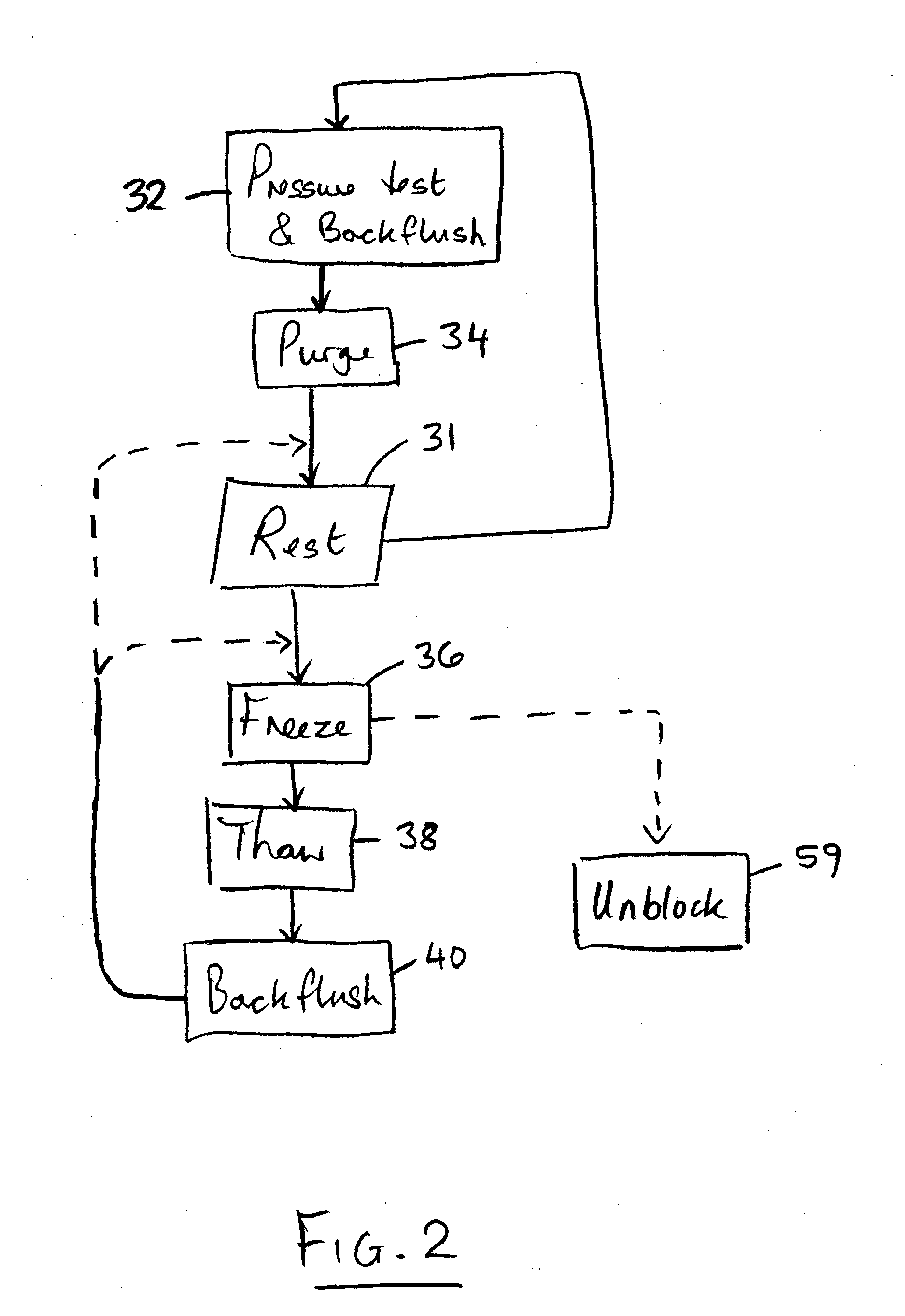
[0007] The backflushing may be carried out when a blockage is detected in use. Additionally or alternatively, the backflushing may be carried out routinely at intervals in use of the cooling device. For example, the backflushing may be carried out following each freeze and / or thaw cycle (or each combined freeze-thaw cycle) of the cooling device. Such frequent backflushing has been found to be highly effective in reducing the risk of occurrence of a blockage, even if the cooling device is used many times.
[0008] A second aspect of the invention may be to use, as a valve between a high pressure refrigerant fluid source, and an inlet side of a cooling device, a valve that is responsive to a pulse modulated electronic control signal. The pulse modulated signal may be a pulse width modulated signal (PWM), or a pulse density modulated (PDM) signal. A pulsed valve may have a fast response, and be less expensive and yet more reliable and durable than an equivalent servo driven valve.
[0009] A third aspect of the invention may be to implement an automatic gradual application of pressure to an inlet side of a cooling device, instead of an abrupt application of refrigerant fluid at high pressure. Such a gradual application of pressure may be referred to as a “soft start”. The gradual application of pressure may help reduce the risk of blockage in the cooling device by avoiding an abrupt pressure wave in the forward direction through the cooling device that may otherwise force foreign matter on the inlet side of the cooling device into the expansion orifice.

Problems solved by technology

A significant problem is that the micro expansion orifice in the probe is vulnerable to blocking by foreign matter such as dust particles or other contaminants that may be contained in the refrigerant fluid or otherwise enter the probe.
For many cyro-surgeons and probe operators, the problem of probe blocking is considered to be a highly inconvenient, yet regular, occurrence that has to be tolerated as a result of the nature of the probe design.
Other problems remain in terms of difficulty of use of the fluid supply apparatus and the probe, difficulty of handling fault conditions such as a blocked or faulty probe, and difficulty of reducing the risk of occurrence of probe blockage.

Method used


Image

  • Method and apparatus for supplying refrigerant fluid
  • Method and apparatus for supplying refrigerant fluid
  • Method and apparatus for supplying refrigerant fluid

Examples


Embodiment Construction

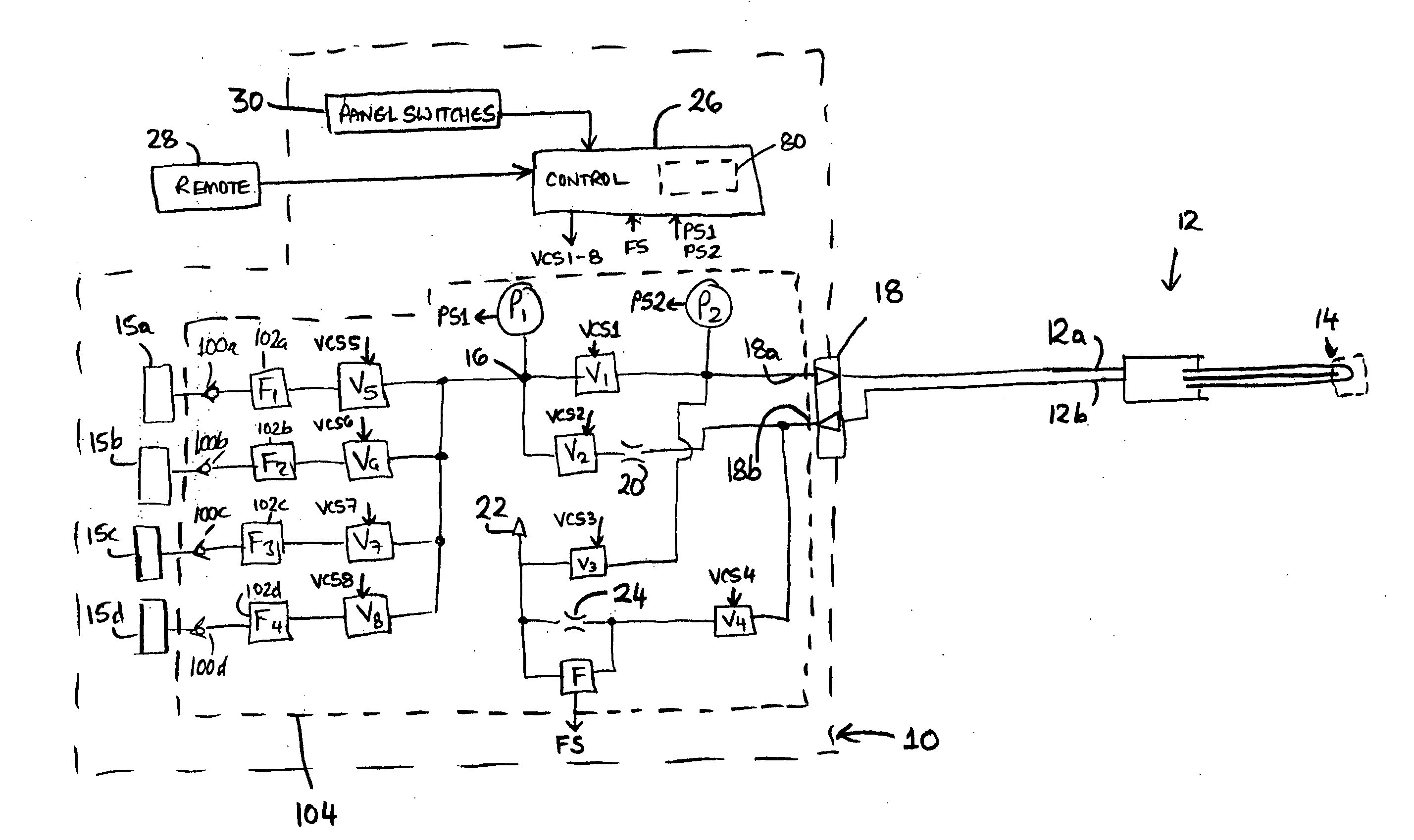
[0022]FIG. 1 may generally illustrate a fluid supply apparatus 10 for supplying and controlling the flow of a refrigerant fluid to a cooling device 12. The cooling device 12 may be detachably connectible to a coupling 18 of the apparatus 10. The cooling device 12 may be a medical or surgical probe. The cooling device 12 may include a small orifice (depicted schematically at 14) for generating a freezing effect by the Joule-Thompson principle of isenthalpic expansion when fluid is forced through the orifice 14 from an inlet side 12a to an outlet side 12b. The terms “inlet side” and “outlet side” may refer to a normal direction of fluid flow through the cooling device 12 for generating the intended freezing effect. The refrigerant fluid may be any suitable fluid for generating significant cooling upon isenthalpic expansion. Such a fluid may often be referred to as a Joule-Thompson fluid and may be a gas. For example, the gas may be nitrous oxide.

[0023] The supply apparatus 10 may gen...


PUM


Abstract

An apparatus is disclosed for supplying a refrigerant fluid to a cooling device, such as a cryosurgical probe. An arrangement of valves may control the supply of fluid to and from the cooling device. Fluid may flow in a forward direction through the cooling device for generating cooling by expansion of the fluid in the cooling device. The apparatus may execute a programmed sequence of cooling and heating cycles automatically. Backflushing of the fluid may be used for clearing contaminants from the inlet side of the cooling device. A pulse width modulated control signal may be used to control one of the valves to have a variable effective aperture. A flow rate sensor may detect the flow rate through the cooling device. The detected flow rate may be used to detect an occurrence of a blockage and / or for controlling the fluid supplied to the cooling device. A blockage may be cleared by automatic backflushing.

Description

FIELD OF THE INVENTION [0001] The present invention may relate to supplying refrigerant fluid to, for example, a cooling device for generating a cooling effect based on Joule-Thompson expansion of the fluid. The invention may be especially useful in the field of medical or surgical use. The cooling device may, for example, be a cooling probe. BACKGROUND TO THE INVENTION [0002] The Joule-Thompson principle of isenthalpic expansion of certain refrigerant fluids (e.g., gases) through a micro expansion orifice has long been used in the medical field to create a freezing effect. Typically, the expansion orifice is located at the tip of a probe through which the refrigerant fluid is driven under pressure. The operation of the probe is controlled by a fluid supply apparatus including one or more valves or regulators for controlling the flow of fluid in the probe. A conventional fluid supply apparatus is described, for example, in WO 00 / 35362. [0003] A significant problem is that the micro ...

Claims


Application Information

Patent Timeline
IPC IPC(8): A61B18/02F25B9/02
CPCA61B18/02F25B9/02A61B2018/0262
Inventor COPPING, GARETH
Owner COPPING GARETH
Learn More