
Internal combustion engine using opposed pistons

a technology of opposed pistons and internal combustion engines, which is applied in the direction of combustion engines, cylinders, positive displacement engines, etc., can solve the problems of low conductivity and high thermal expansion coefficient of hollow tubes, and achieve low weight to power ratio, low emissions, and low fuel consumption.

Inactive Publication Date: 2005-04-21
MECHANICAL INNOVATION
View PDF17 Cites 22 Cited by
  • Summary
  • Abstract
  • Description
  • Claims
  • Application Information

AI Technical Summary

Benefits of technology

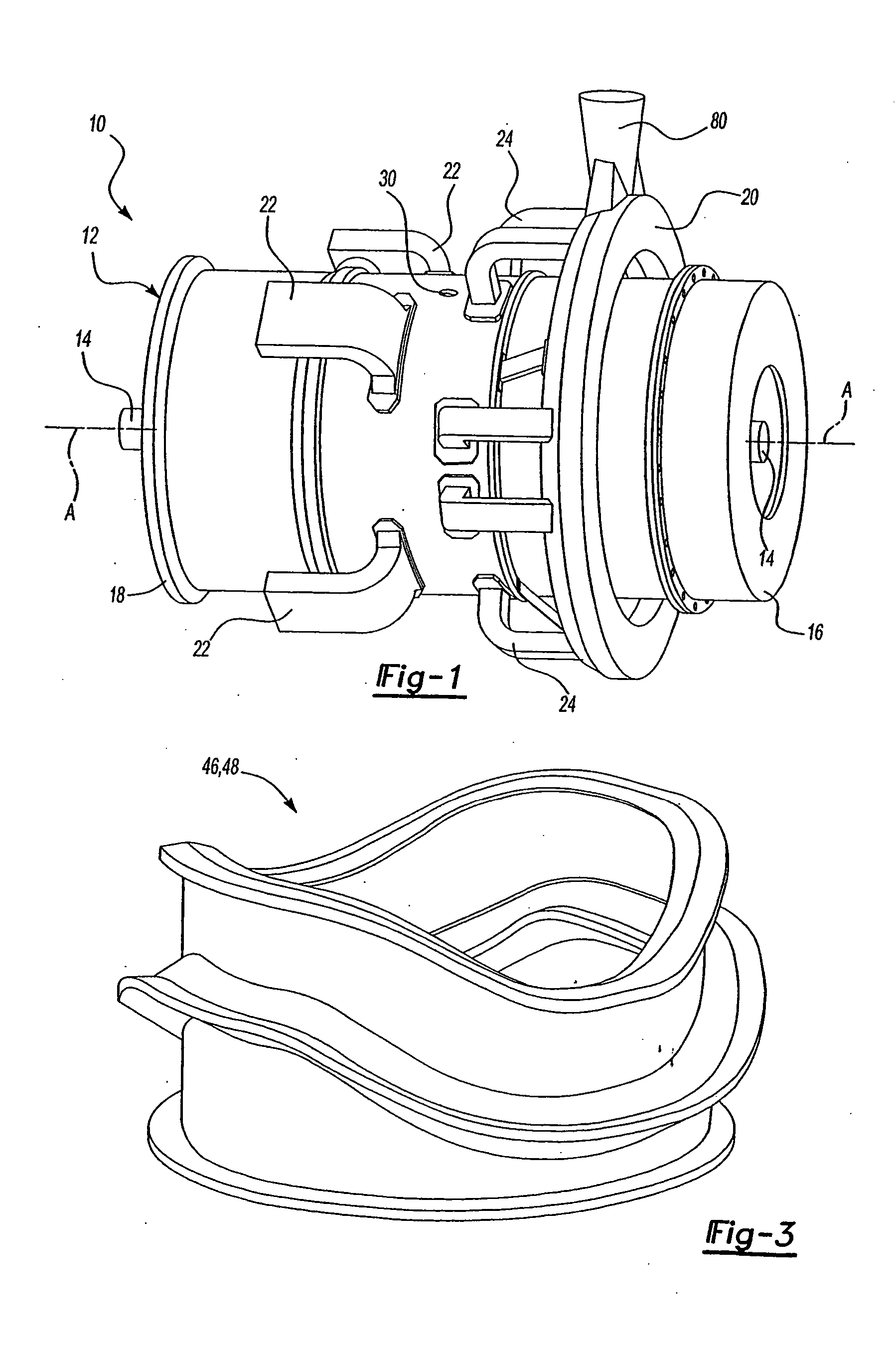
[0008] The present invention provides an improved internal combustion engine that has a low weight to power ratio, low emissions and low fuel consumption. The engine of the present invention provides numerous improvements over known internal combustion engines.
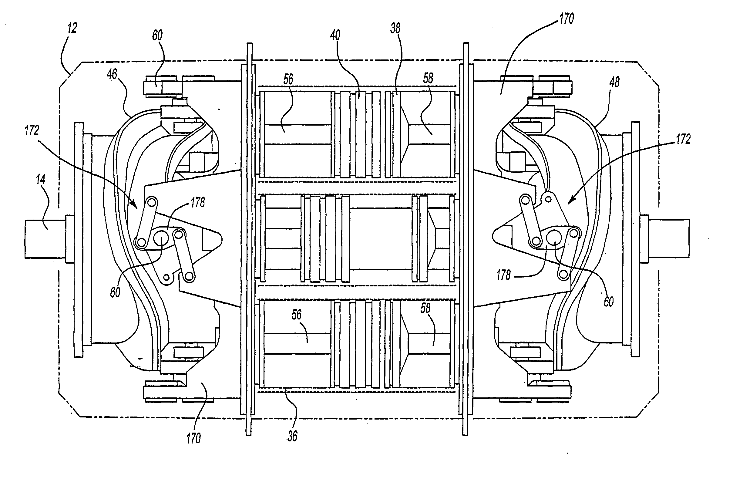
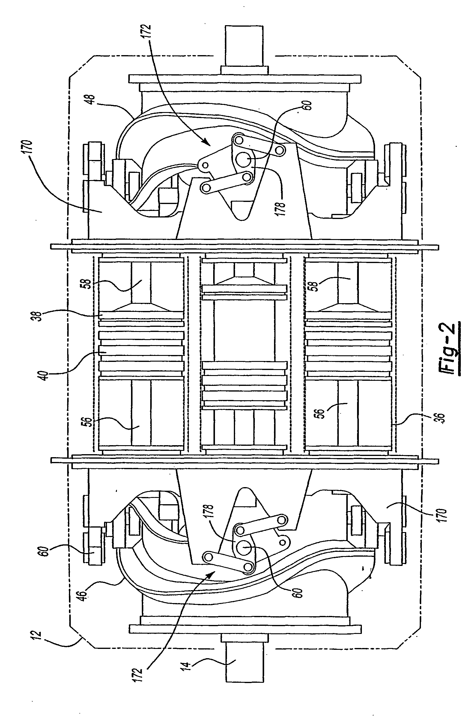
[0009] The present invention includes an internal combustion engine having a housing enclosing at least one cylinder with opposed pistons mounted for reciprocation within the cylinder. Opposed power cams are mounted upon a power output shaft. Each of the power cams are operatively connected to a respective one of the opposed pistons. End plates are mounted to the housing and divide the housing into a center section and end sections. At least one cylinder with opposed pistons mounted for reciprocation within the cylinder is mounted within the center section and one each of the opposed power cams is mounted within a respective one of the end sections. The opposed pistons have connecting rods operatively interconnecting the pistons to the cams. The end plates have openings for reciprocal receipt of the connection rods. Unique seals are provided to seal the end sections from the center sections and to seal the cylinders to the end plates. The entire engine of the preferred embodiment is designed to maintain all spring rates at acceptable rates to avoid any inadvertent weakening of connections in the engine.
[0016] The pistons of the present invention are also uniquely designed to include facing combustion surfaces with outer perimeters, the outer perimeters of the combustion surfaces each having a profiled surface, the profiled surfaces mate to form a combustion chamber between the piston combustion surfaces. This allows the combustion surface to be generally closed to reduce heat loss from the combustion chamber during combustion.

Problems solved by technology

This first hollow tube has a high thermal expansion coefficient and low conductivity.

Method used


Image

  • Internal combustion engine using opposed pistons
  • Internal combustion engine using opposed pistons
  • Internal combustion engine using opposed pistons

Examples


Embodiment Construction

[0049] In its preferred embodiment, the engine of the present invention as described herein is configured with four (4) cylinders and eight (8) pistons and each paired diametrically opposed piston sets are compressing and expanding axi-symmetrically, so as to minimize or eliminate unbalance or out of plane loads at any time during the engines operating envelope for providing a relatively vibration free engine. Since each piston set “fires” twice per output shaft revolution, it produces twice the torque at half the shaft RPM. While this invention is described in the preferred embodiment to include specific parameters, it will be appreciated by one skilled in this art that other parameters including the number of pistons and attendant cylinders could be used without departing from the scope of this invention. It will be appreciated that two opposing pistons in a single cylinder will constitute the minimum number of pistons and cylinders, it will also be appreciated that more or less t...


PUM


Abstract

An internal combustion engine having a cylindrical outer housing with inner cylindrical cylinders defining power cylinders circumferentially spaced in the engine. Each of the cylinder(s) has opposed intake and exhaust pistons. The intake and exhaust pistons use air bearings instead of conventional oil as a lubricant. The intake and exhaust pistons power a rotary cam mounted on opposed ends of the engine and a cam follower system positions the pistons. The rotary cam is operatively connected to a drive shaft or power take off shaft. A four bar linkage system is connected to the piston rod to minimize piston side loads. A jumper connects the ends of the power cylinders to pressurize air drawn into the engine and to admit heated air, indirectly heated during the combustion cycle, to charge the power cylinder for improved efficiency and to purge the pressure cylinder after combustion. The overall construction of the engine allows the engine to be made from relatively light weight materials providing a significantly improved power to weight ratio over conventional engines. The overall construction also allows for reduced fuel emissions and greater fuel efficiency.

Description

TECHNICAL FIELD [0001] This invention relates to reciprocating internal combustion engines and particularly to an advanced version that eliminates side loadings, utilizes thermally controlled power cylinders, opposed intake and exhaust pistons, piston rings that are cooled and hydrostatically lubricated by air, and incorporates a high temperature cylinder wall which reduces engine emissions and increases engine performance. BACKGROUND [0002] As is well known, diesel, gas and steam engines of the reciprocating type typically convert the linear piston motion into rotary motion by utilizing piston(s), connecting rod, and crankshaft. This conversion process obviously creates a substantial piston side load which requires oil lubrication to control friction and wear of the piston skirt and cylinder and a substantial and heavy engine case. To prevent oil breakdown and loss of lubricity the cylinder wall and piston side walls and rings generally are maintained at a temperature that is below...

Claims


Application Information

Patent Timeline
Patent Type & Authority Applications(United States)
IPC IPC(8): F01B3/00F02B75/28F01B3/04F01B9/06F02B25/08F02B67/00F02B75/26F02B77/00F02F1/16F02F1/24F16J9/00F16J10/02
CPCF01B3/0005F02B75/282F02B75/26
Inventor NOVOTNY, RUDOLPH J.
Owner MECHANICAL INNOVATION
Learn More