
PEM Fuel Cell Stack

a fuel cell and polymer membrane technology, applied in the field of fuel cells, can solve the problems of reducing the output power of the stack, reducing the working pressure of the fuel cell, and limiting the air-cooled proton exchange membrane with the polymer electrolyte membrane, so as to improve the cooling efficiency, increase the working pressure of the fuel cell, and improve the effect of power to weight ratio

Active Publication Date: 2014-09-18
WUHAN TROOWIN POWER SYST TECH
View PDF1 Cites 1 Cited by
  • Summary
  • Abstract
  • Description
  • Claims
  • Application Information

AI Technical Summary

Benefits of technology

The invention provides a flow field plate assembly for a proton exchange membrane fuel cell that allows for a higher working pressure and improves cooling efficiency. This results in a greater power to weight ratio and enhances the overall viability of fuel cells as an energy source. The assembly also allows for safer operation and improved kinetics, cell uniformity, and response to load change. The design reduces the overall weight to power ratio and the sensitivity of membrane water content to fan speed. Additionally, the assembly can be adapted to mount on most conventional proton exchange membrane fuel cells.

Problems solved by technology

One of the main flaws in an air-cooled proton exchange membrane fuel cell with polymer electrolyte membrane is thermal and water management.
An inappropriate fan speed would reduce output power of the stack.
Another limitation of the air-cooled proton exchange membrane with polymer electrolyte membrane is hydrogen leaking.
However, higher hydrogen pressure can help improve the kinetics, cell uniformity, response to load change and reduce the probability of hydrogen starvation which is extremely detrimental to fuel cell durability, but pressure above this level may cause a leak or gasket to burst.

Method used


Image

  • PEM Fuel Cell Stack
  • PEM Fuel Cell Stack
  • PEM Fuel Cell Stack

Examples


Embodiment Construction

[0033]The following description is disclosed to enable any person skilled in the art to make and use the present invention. Preferred embodiments are provided in the following description only as examples and modifications will be apparent to those skilled in the art. The general principles defined in the following description would be applied to other embodiments, alternatives, modifications, equivalents, and applications without departing from the spirit and scope of the present invention.

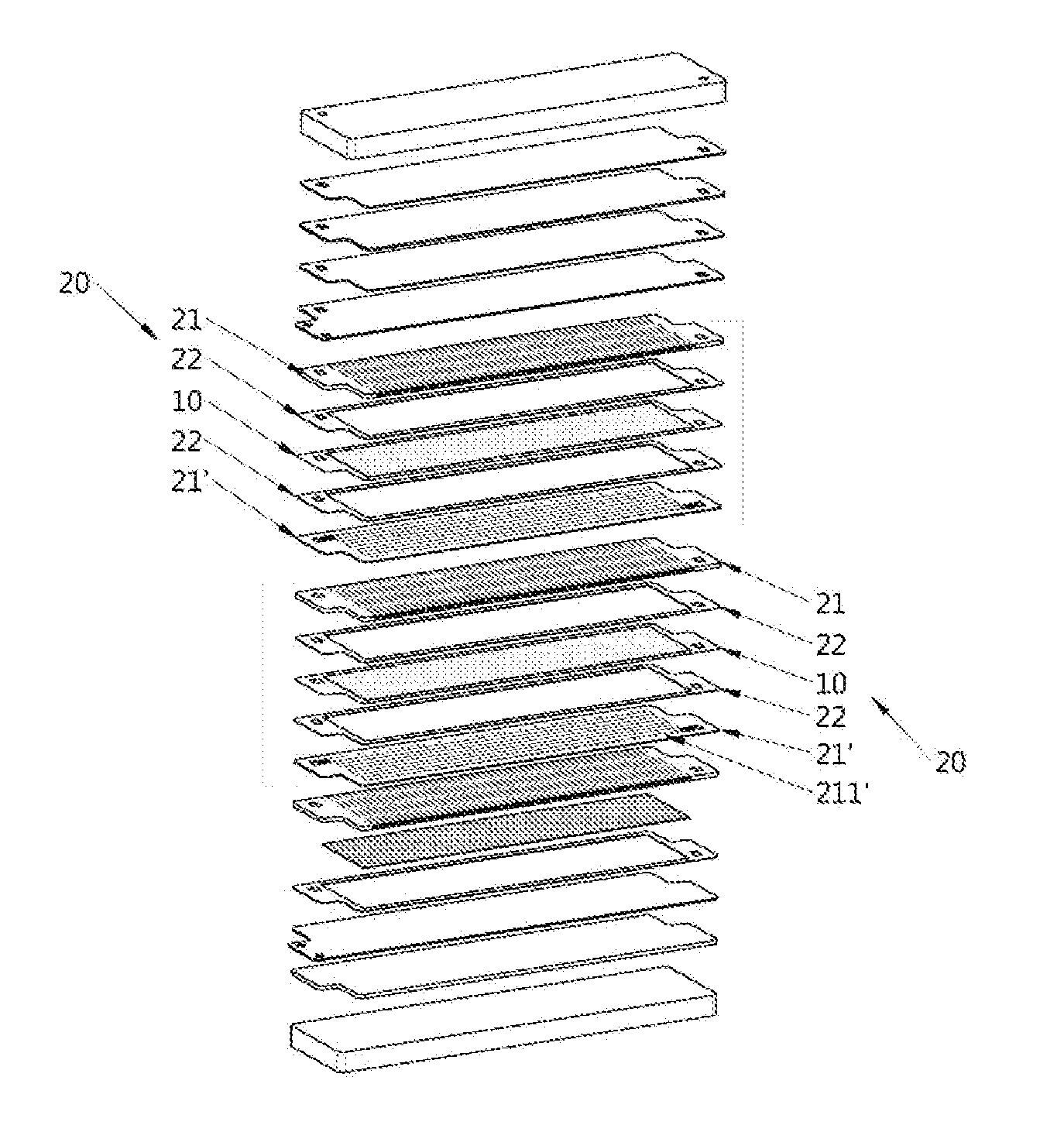
[0034]As shown in FIG. 3, a PEM fuel cell stack in the preferred embodiment of the present invention is illustrated. The fuel cell stack comprises one or more fuel cell unit being stacked with each other. According to the preferred embodiment, each fuel cell unit, which can be formed as a single fuel cell, comprises a membrane electrode assembly (MEA) 10 and a flow field plate assembly 20 which comprises two electrically conductive dipolar plates for sandwiching the MEA 10 therebetween.

[0035]The ...


PUM

PropertyMeasurementUnit
thicknessaaaaaaaaaa
open circuit voltageaaaaaaaaaa
electrical energyaaaaaaaaaa

Abstract

A fuel cell includes a cathode flow field plate, an anode flow field plate, and a membrane electrode assembly (MEA) sandwiched between the cathode and anode flow field plate. The cathode flow field plate has a flat side and an opposed channel side that the MEA is sandwiched between the anode flow field plate and the flat side of the cathode flow field plate. The cathode flow field plate further has a plurality of flow channels formed at the channel side for enabling fluid flowing along the flow channels to promote electrochemical reaction through the MEA so as to generate electrical energy.

Description

NOTICE OF COPYRIGHT[0001]A portion of the disclosure of this patent document contains material which is subject to copyright protection. The copyright owner has no objection to any reproduction by anyone of the patent disclosure, as it appears in the United States Patent and Trademark Office patent files or records, but otherwise reserves all copyright rights whatsoever.BACKGROUND OF THE PRESENT INVENTION[0002]1. Field of Invention[0003]The present invention relates to the field of fuel cells, and more particularly in the field of polymer membrane fuel stacks for use in a proton exchange membrane fuel cell.[0004]2. Description of Related Arts[0005]A fuel cell is an energy source that converts the chemical energy from a fuel into electricity through a chemical reaction with oxygen or another oxidizing agent. Hydrogen is most commonly used as the fuel for these types of cells. One of the most representative embodiments of this fuel cell technology is the proton exchange membrane (PEM)...

Claims


Application Information

Patent Timeline
Patent Type & Authority Applications(United States)
IPC IPC(8): H01M8/02
CPCH01M8/0258H01M8/0267H01M8/0273H01M8/1004H01M8/241H01M8/2483Y02E60/50
Inventor LI, XIAO
Owner WUHAN TROOWIN POWER SYST TECH
Learn More