
Total heat exchanging element

a technology of heat exchange element and total amount, which is applied in the field of total heat exchange element, can solve the problems of limited total amount of chemicals capable of application or impregnation to a unit area of the base material of the partition member, difficult to achieve the exchange efficiency higher than with a moisture absorbent alone, and only a limited choice of flame retardants, so as to improve the effect of moisture permeation and improve the efficiency of heat exchange and flame retardancy

Inactive Publication Date: 2005-04-21
MITSUBISHI ELECTRIC CORP +1
View PDF5 Cites 22 Cited by
  • Summary
  • Abstract
  • Description
  • Claims
  • Application Information

AI Technical Summary

Benefits of technology

[0017] The present invention has been achieved to solve the foregoing problems. It is thus a first object of the present invention to prevent the effect of the moisture absorbent or other materials for providing moisture permeability from being hampered by the flame retardant or other materials for providing flame retardancy, thereby eliciting the effect of moisture permeation so that the total heat exchanging element improves in the efficiency of heat exchange.
[0018] A second object of the present invention is to allow the amounts of use of the moisture absorbent or other materials for providing moisture permeability and the flame retardant or other materials for providing flame retardancy to be set freely without restriction on each other, and allow the two to be selected irrespective of reactivity with each other so that the total heat exchanging element improves in the efficiency of heat exchange while achieving flame retardancy.
[0020] Since the moisture permeable portions provided with moisture permeability and the flame resisting portions provided with flame retardancy of the partition members and spacing members do not overlap each other within each single member, the effect of the moisture absorbent or the like for providing moisture permeability is not hampered by the overlap with the flame retardant or the like for providing flame retardancy, so that it is possible to elicit the effect of moisture permeation. As a result, it is possible to improve the effect of moisture permeation, so that the total heat exchanging element achieves both an improved efficiency of heat exchange and flame retardancy.

Problems solved by technology

Nevertheless, such conventional configurations with the overlapping flame retardant and moisture absorbent have the following problems.
Nevertheless, the maximum total amount of chemicals capable of application or impregnation to a unit area of the base material of the partition member is limited.
The same holds vice versa, adding up to another problem of a trade-off between the moisture absorbability and the flame retardancy.
This means another problem which is a narrow choice of the moisture absorbent and the flame retardant.
This moisture absorbability, however, is not as high as that of a moisture absorbent, and it is therefore difficult to achieve exchange efficiency higher than with a moisture absorbent alone.
In addition, the same problem as the foregoing problem 3) also occurs in that such a flame retardant has only a limited choice.

Method used


Image

  • Total heat exchanging element
  • Total heat exchanging element
  • Total heat exchanging element

Examples


first embodiment

[0025] A total heat exchanging element according to a first embodiment of the present invention will be described in more detail with reference to the accompanying drawings.

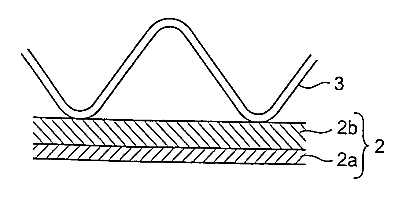
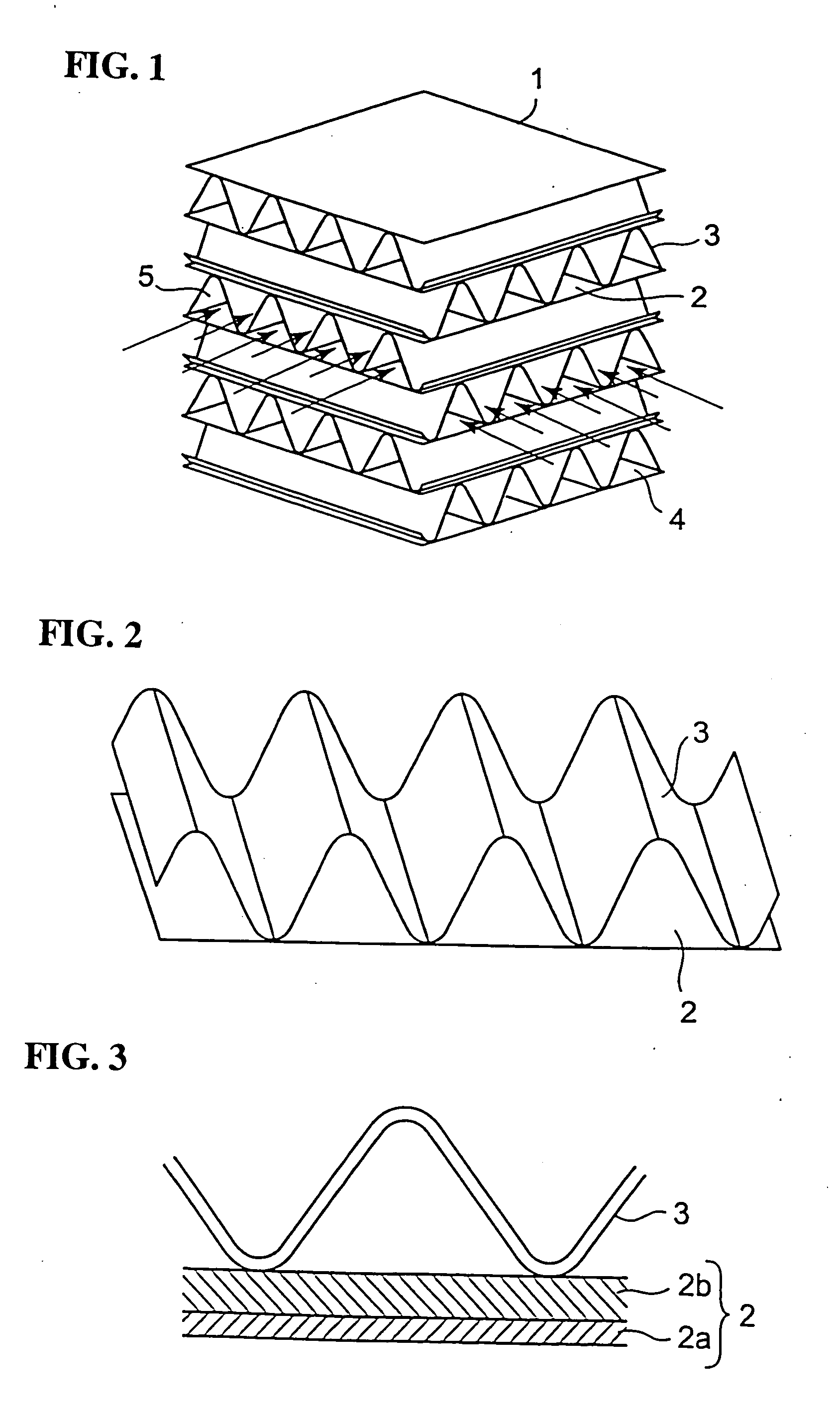
[0026]FIG. 1 shows the total heat exchanging element 1 according to the first embodiment of the present invention. The total heat exchanging element 1 is composed of partition members 2 and spacing members 3 which are laminated alternately. The partition members 2 have a flat shape. The spacing members 3 have a corrugated section of serrate shape, sinusoidal shape, or the like. The spacing members 3 are formed so that their projections onto the planes of the partition members 2 coincide with the partition members 2. As shown in FIG. 2, a unit component member is fabricated by laminating a single partition member 2 and a single spacing member 3 so as to make contact at the convex portions of the corrugated shape, and fixing the same by such means as adhesive bonding. Such unit component members are laminated with...

second embodiment

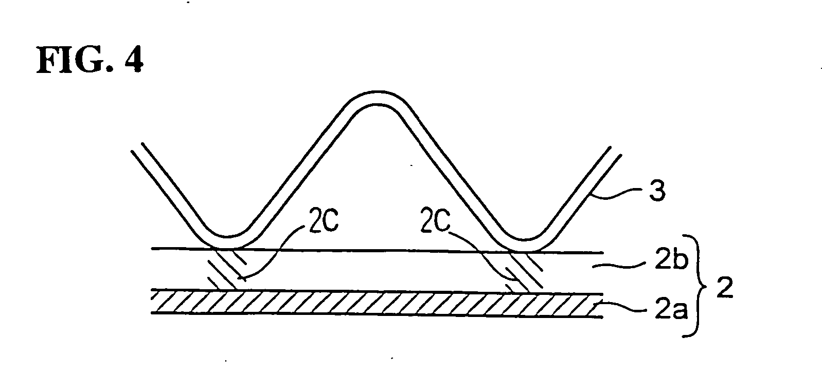
[0047]FIG. 4 is a sectional view showing the total heat exchanging element according to a second embodiment of the present invention. This sectional view is of the unit component member in FIG. 2, taken along a direction perpendicular to the airflow path formed by the spacing member.

[0048] In this total heat exchanging element 1,a flame retardant 2c (guanidine-salt flame retardant) is applied to specified areas of the base material 2a of the partition member 2, where the partition member 2 is in contact with the spacing member 3, and a moisture absorbent 2b to the other areas. The moisture absorbent 2b consists chiefly of an alkali metal salt such as lithium chloride and calcium chloride. The spacing member 3 is made of flame-retarded paper which is impregnated with a guanidine-salt flame retardant such as guanidine chloride and guanidine sulfamate. The partition member 2 is pasted to the same spacing member 3 as that of the first embodiment by an adhesive (such as vinyl acetate ty...


PUM

PropertyMeasurementUnit
Permeabilityaaaaaaaaaa

Abstract

When latent heat is transferred between the two airflows flowing along the respective sides of each partition member, not only a layer of moisture absorbent but also a layer of flame retardant lies in the direction of transfer of the moisture. Thus, even if the moisture is absorbed by the layer of moisture absorbent, the layer of flame retardant resists the moisture transfer so that the amount of transfer of the moisture decreases in that part with a drop in the moisture permeability of the partition member. To solve the problem, there is provided a total heat exchanging element comprising partition members and spacing members having moisture permeable portions provided with moisture permeability and flame resisting portions provided with flame retardancy, the both portions not overlapping with each other within each single member. For example, the partition members have the moisture permeable portions provided with moisture permeability, and the spacing members have the moisture resisting portions provided with flame retardancy.

Description

BACKGROUND OF THE INVENTION [0001] 1. Field of the Invention [0002] The present invention relates to a heat exchanging element of laminated structure for use in a heat exchanging apparatus for conducting heat exchange between two fluids in the field of air conditioning. In particular, the invention relates to a total heat exchanging element for exchanging both latent heat and sensible heat. [0003] 2. Description of the Related Art [0004] A total heat exchanging element of laminated structure typically used in the field of air conditioning heretofore comprises basic component members each of which is formed by laminating a partition member of flat shape and a spacing member of corrugated section. Here, the basic component members are laminated and bonded so as to make the directions of corrugation in their spacing members have substantially right angles with each other. The spacing members of this total heat exchanging element form flow paths. Airflows of different states (typically,...

Claims


Application Information

Patent Timeline
IPC IPC(8): F24F7/08F24F3/147F28D9/00F28D9/04F28D21/00F28F3/02F28F3/08F28F21/00
CPCF24F3/147F28D21/0015F28D9/0062F24F2003/1435D21H17/66D21H21/16D21H21/34D21H27/40D21J1/08F24F13/30F28D9/02F28F21/00F28F3/02F28D9/04
Inventor TAKADA, MASARUARAI, HIDEMOTOSUGIYAMA, YOUICHIYOKOYA, HISAOTAKAHASHI, KENZOHARADA, JUNJITSUBAKI, MASAYUKI
Owner MITSUBISHI ELECTRIC CORP
Learn More