Chromatography cartridge and method for manufacturing a chromatography cartridge

a technology of chromatography and chromatography cartridge, which is applied in the direction of filtration separation, separation processes, instruments, etc., can solve the problems of liquid not being used, not being able to achieve the desired effect, and not being able to achieve repeatability, accurate results, and reduced channeling

Inactive Publication Date: 2005-04-21
AGILENT TECH INC
View PDF31 Cites 30 Cited by
  • Summary
  • Abstract
  • Description
  • Claims
  • Application Information

AI Technical Summary

Benefits of technology

[0004] The method used to manufacture a chromatography cartridge can reduce channeling. For example, channeling can be controlled by the method used to couple an endcap to a housing portion of the cartridge. The method of coupling the endcap can affect, among other things, whether a hermetic (leak-proof) seal is established in the cartridge, whether the chromatography media is tightly packed within the cartridge, whether the chromatography media is maximally used in separation of various components of the liquid phase, and whether the chromatography system will produce repeatable, accurate results.

Problems solved by technology

When the cartridge is used, “channeling” can result if the media is not tightly packed.
If an easy flow path is available to the liquid because the media is not tightly packed, the liquid may not interact as desired with the rest of the media.
Therefore, much of the media will not be used, which may affect the performance of the chromatography cartridge and the accuracy of the chromatography results.

Method used


Image

  • Chromatography cartridge and method for manufacturing a chromatography cartridge
  • Chromatography cartridge and method for manufacturing a chromatography cartridge
  • Chromatography cartridge and method for manufacturing a chromatography cartridge

Examples


Embodiment Construction

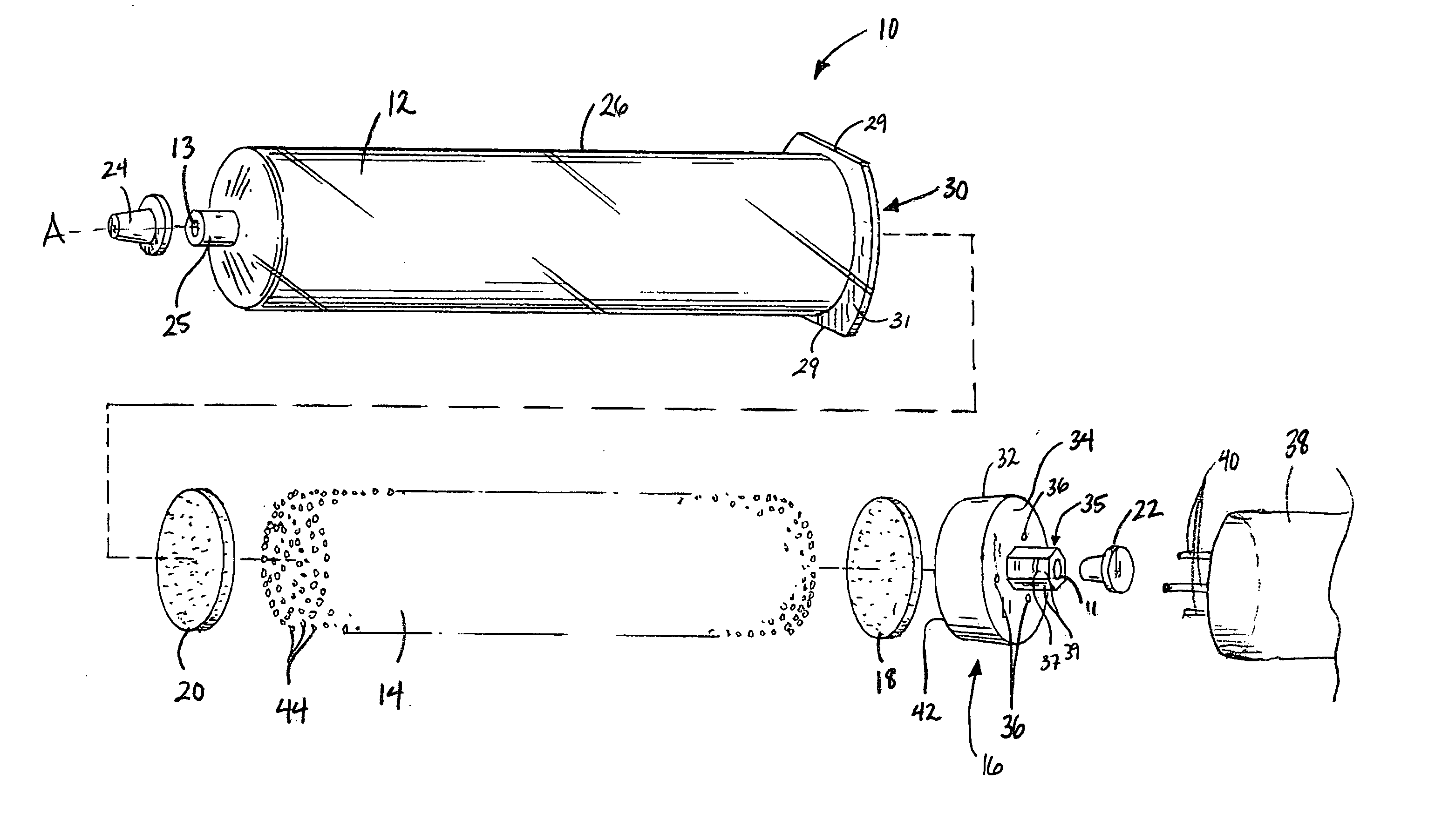
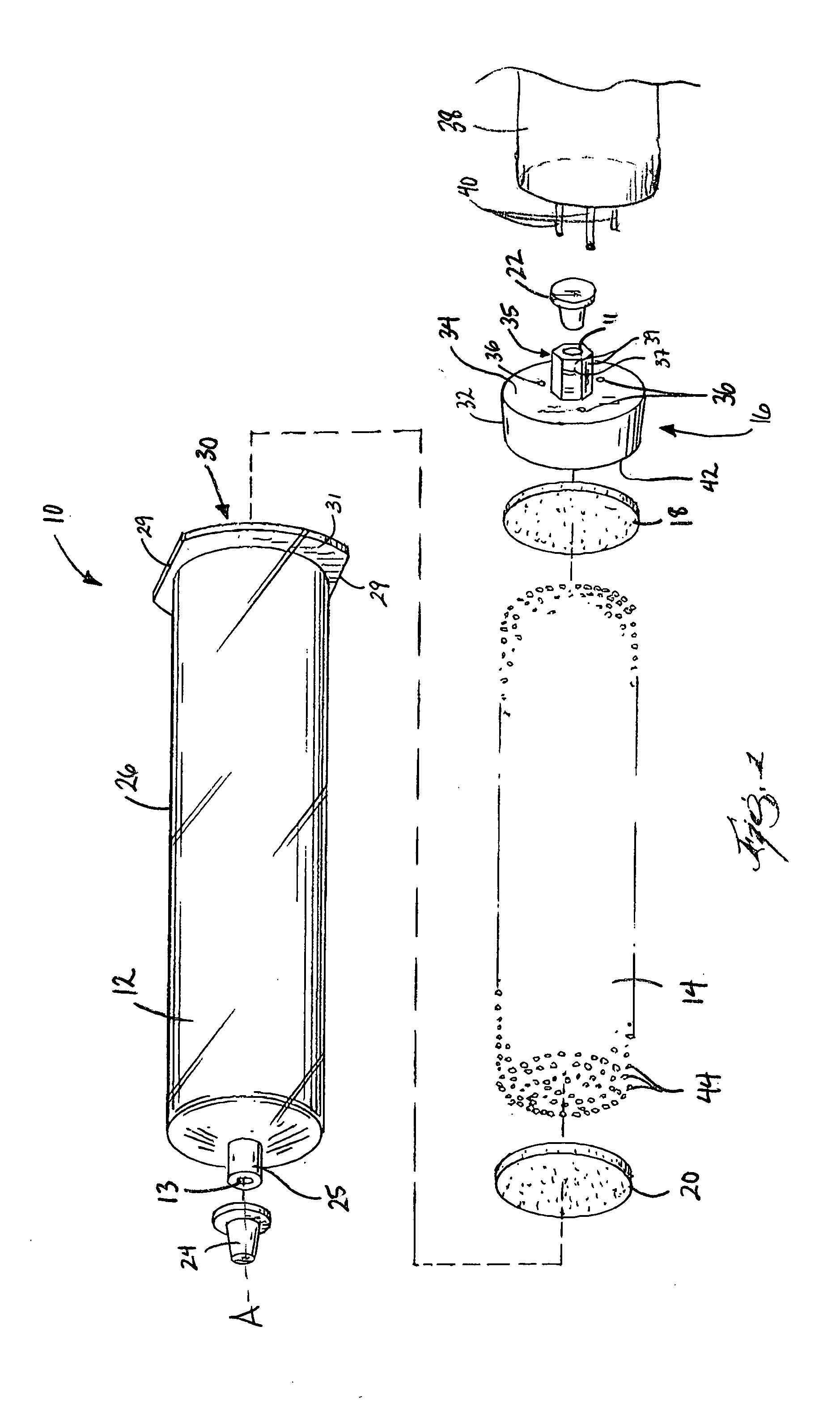
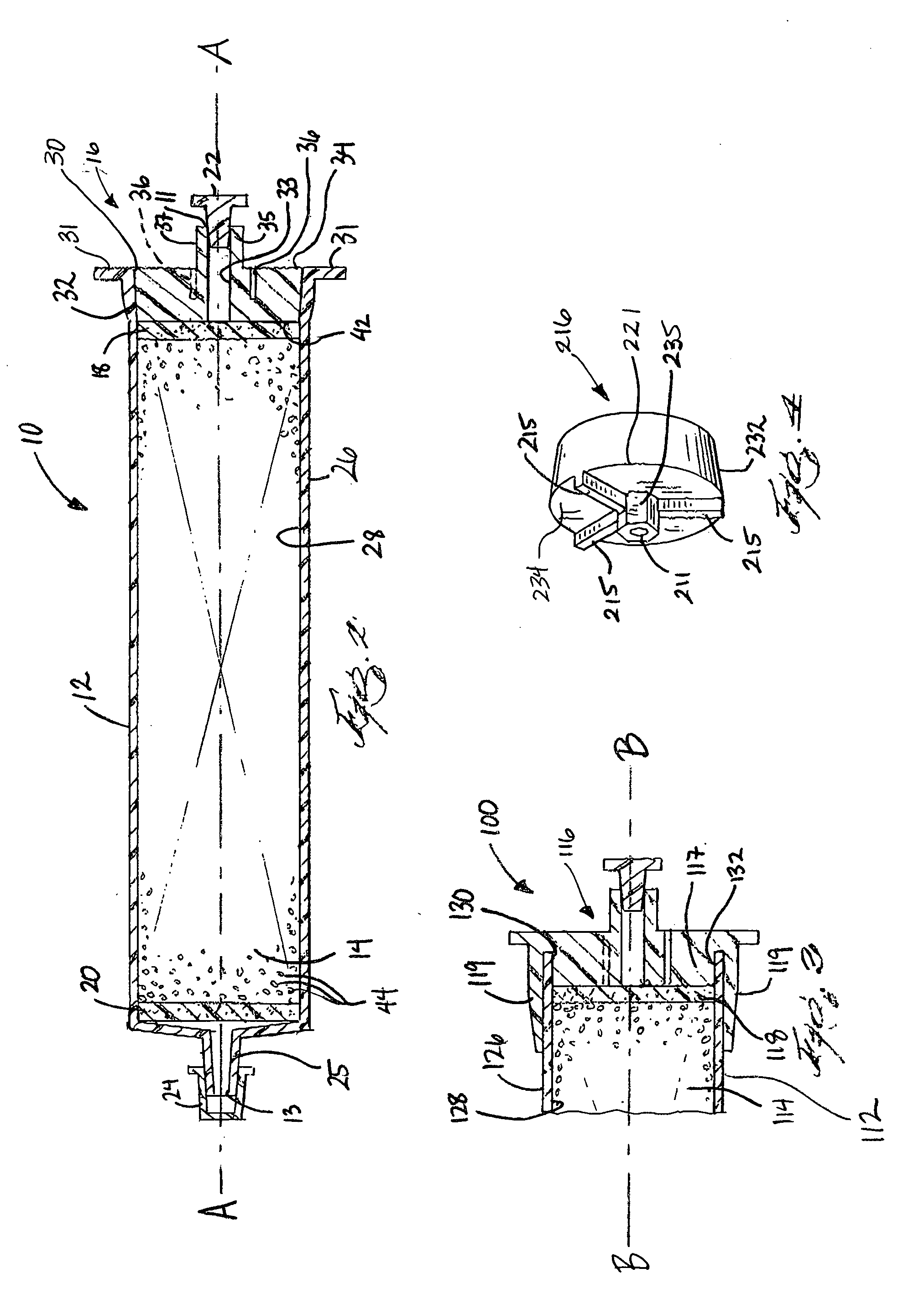
[0014]FIGS. 1 and 2 illustrate a chromatography cartridge 10 (also referred to herein as a chromatography “column”) according to one embodiment of the present invention. The cartridge 10 contains at least one chromatography medium 14 (also referred to herein as a “stationary phase”), and an inlet 11 and an outlet 13 for fluid flow through the cartridge 10 and thereby the medium 14. The medium 14 is bounded on a first end by a first frit 18 or other porous member positioned towards the inlet 11, and on the second end by a second frit 20 positioned towards the outlet 13. The medium 14 is contained within a housing 12 that is capped on one end by a plug 16 (also referred to herein as and “endcap”). The plug 16 defines the inlet 11 to the cartridge 10. A first cap 22 is dimensioned to be received within the inlet 11 during transportation and storage, and a second cap 24 is dimensioned to cover the outlet 13 during transportation and storage.

[0015] The chromatography cartridge 10 can be...


PUM

PropertyMeasurementUnit
particle diametersaaaaaaaaaa

Abstract

A chromatography cartridge and method of manufacturing same. A chromatography cartridge of the present invention can include a tubular housing having an open end and an inner surface, and a plug. The plug can be positioned within the open end of the tubular housing and can have an outer circumferential surface, a substantial portion of the outer circumferential surface being fused to the inner surface of the tubular housing. A method for manufacturing a chromatography cartridge can include coupling at least a portion of the outer surface of the plug to at least a portion of the inner surface of the tubular housing in response to rotating at least one of the plug and the tubular housing about the longitudinal axis with respect to the other of the plug and the tubular housing.

Description

RELATED APPLICATIONS [0001] This application claims the benefit of U.S. Provisional Patent Application Serial No. 60 / 512,129, filed Oct. 17, 2003.BACKGROUND OF THE INVENTION [0002] Chromatography columns or cartridges typically contain a densely-packed chromatography media (sometimes referred to as the “stationary phase”). When liquid (sometimes referred to as the “liquid phase”) is passed through the chromatography cartridge, at least a portion of the liquid phase adsorbs to the stationary phase within the cartridge. In this way, those components of the liquid phase that adsorb to the stationary phase are separated out from those that do not. Based on the different adsorption rates of various components of the liquid phase, the various components of the liquid phase can be isolated and identified. [0003] When the cartridge is used, “channeling” can result if the media is not tightly packed. If the media is not tightly packed, the liquid phase in the chromatography system may find a...

Claims


Application Information

Patent Timeline
Patent Type & Authority Applications(United States)
IPC IPC(8): B01D15/22G01N30/60
CPCB01D15/22G01N30/6091Y10T29/49968G01N30/6004Y10T29/49604
Inventor DEMARCO, NICHOLAS
Owner AGILENT TECH INC
Why Eureka
Try Eureka