Multi directional device for vapor-solid mixing

a multi-directional device and vapor solid technology, applied in the field of internals, can solve the problems of increasing the combustion load of the regenerator, affecting the final yield of the converted product, and affecting the stripping operation, so as to achieve the effect of increasing the flow area, increasing the surface area, and increasing the mixing intensity

Active Publication Date: 2018-12-11
TECH PRECESS TECH INC
View PDF16 Cites 5 Cited by
  • Summary
  • Abstract
  • Description
  • Claims
  • Application Information

AI Technical Summary

Benefits of technology

[0021]As disclosed further herein below, by splitting the blades and varying their orientation within the packing system improved mass transfer is accomplished through increased surface area, intensity of mixing, as well as increased area of flow for the gas and solid phases within the packing system. The claimed packing system is advantageous for reducing channeling and phase separation around the blades, allows portion of catalyst to shower down through the gas flowing up from underneath the lower portion of the blade, thus increasing stripping gas utilization as well as capacity.
[0022]The claimed structured packing system provides more open space within the stripping vessel and has less tendency for back-mixing and channeling. Further, the claimed structured packing system is lighter than prior art packing structures due to the splits in the blades, thus making its support easier and less costly.
[0023]The embodiments disclosed herein, individually or combined provide improved mass transfer and / or catalyst stripping. The claimed packing system is applicable to any gas solids stripping or reaction process, for example, when utilized with FCC technology the system provides: improved product retention / recovery; reduced “fuel” to regenerator through reduced regenerator temperature and increased catalyst circulation; reduced steam consumption; improved heat buildup; increased catalyst circulation capacity; reduced steam consumption; reduced costs; improved stripper pressure build up; improved hydraulics via better fluidization; improved flexibility; and overall weight reduction.

Problems solved by technology

In fact, insufficient stripping results in the reactor effluent remaining on and in between the catalyst particles so that during the regeneration step an additional combustion load is imposed upon the regenerator with excessive heat production beyond the heat needed to drive the catalytic reaction.
As a result, the combustion of entrained hydrocarbon vapors into the regenerator represents a loss in final yield of converted product.
Moreover, the stripping operation is challenging.
In particular, it is difficult to control the travel of the catalyst particles and to avoid partial de-fluidization linked with channeling (direct passage of large bubbles through the fluidized bed) and with back-mixing (downflow of poorly fluidized particles or even recirculation of such particles, especially in the region of the stripping chamber wall).
Thus, the range of and average stripping time of deactivated catalyst particles and the quality of contact between grains and gaseous fluid are difficult to control particularly in fluidized beds of large volume.
The excess steam increases the gas and liquid load on equipment connected to the stripper.
For example, the excess steam can increase the quantity of sour water produced per pound of hydrocarbon processed, as well as increase the operating costs for producing and processing the excess steam.
Current structured packing elements have various limitations, for example, reduced mixing of the stripping gas and catalyst because a portion of gas stream tends to flow up along the underside of planar portions or blades and a portion of catalyst stream tends to flow down the top side of the blade with little or no interaction between the gas and catalyst.
Despite the flow direction of each element or layer of elements being 90° oriented to each other the continuous blade surfaces do not provide good redistribution of catalyst and gas throughout the depth of the fluidized bed.

Method used


Image

  • Multi directional device for vapor-solid mixing
  • Multi directional device for vapor-solid mixing
  • Multi directional device for vapor-solid mixing

Examples


Embodiment Construction

[0030]Embodiments of the disclosure are described more fully hereinafter with reference to the accompanying drawings, in which example embodiments of the disclosure are shown. This disclosure may, however, be embodied in many different forms and should not be construed as limited to the example embodiments set forth herein; rather, these embodiments are provided so that this disclosure will be thorough and complete, and will fully convey the scope of the embodiments to those skilled in the art. Like numbers refer to like, but not necessarily the same or identical, elements throughout.

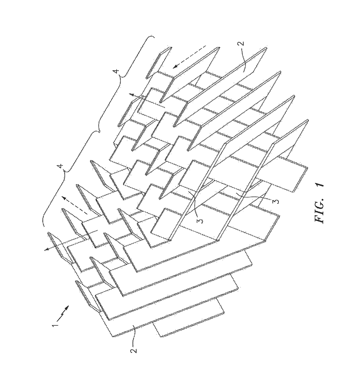
[0031]FIG. 1 presents two element structures (4) of the claimed packing system (1). Each element structure (4) contains a plurality of substantially flat planar baffles or blade structures, i.e., blades (2). Each blade (2) has a plane that provides a direction for the gas and solids to flow along. The plurality of planar blades (2) are arranged in alternating intersecting planes and provide a plurality ...


PUM


Abstract

A packing system is disclosed that has a series of flat blades arranged to promote mixing in a fluidized bed such as one in a FCC stripper, with an upward flowing gas stream and a downward flowing solid particle stream. The blade arrangement provides for different gas solids flow directions within a single layer of packing system to enhance cross mixing of gas and catalyst in all directions and reduces the potential for gas and catalyst bypassing. The blade arrangement has splits which minimizes the tendency for phase separation around the blade. The arrangement and sizing of the blades is intended to promote intimate contact between the two phases to ensure efficient mass transfer of material trapped inside the particles to the gas phase. The arrangement of the blades prevents excessive bubble growth and channeling, both of which reduce surface area for mass transfer.

Description

FIELD OF THE INVENTION[0001]The present disclosure relates to internals utilized in fluidized beds in which solid particulates and fluids flow in a countercurrent relationship. More particularly, the embodiments disclosed herein are directed to packing elements comprising of multiple baffles, utilized to facilitate contact between the solid particulates and fluids in the fluidized bed.DESCRIPTION OF THE RELATED ART[0002]The Fluidized Catalytic Cracking (FCC) process is a chemical process commonly used in oil refineries, the purpose of which is to convert heavy, high molecular weight hydrocarbon materials into lighter lower molecular weight hydrocarbon fractions. In this type of process a hydrocarbon feedstock is vaporized at high temperatures and at the same time placed in contact with the particles of the cracking catalyst maintained in suspension in the feedstock vapor and entrained thereby. After the cracking reactions have produced the desired molecular weight range with a corre...

Claims


Application Information

Patent Timeline
Patent Type & Authority Patents(United States)
IPC IPC(8): B01J8/00B01J8/24B01J8/34B01J8/18B01J8/08B01J8/38B01D53/12B01D15/18B01J19/32
CPCB01D15/1807B01J8/34B01J8/382B01J8/082B01J2219/32466B01D53/12B01J19/32B01J2219/32268B01J2219/32286B01J2219/32296B01J2219/3325B01J19/006B01J2219/0077
Inventor MARCHANT, PAULSINGH, RAJ KANWAR
Owner TECH PRECESS TECH INC
Why Eureka
Try Eureka