
Holding device with moment limiting means for objects to be screwed in components

a technology of holding device and component, which is applied in the direction of intravenous device, transportation and packaging, brake system, etc., can solve the problems of relatively soft piston jumping, piston rotation or displacement, and screwing in problems, and achieves the elimination of disadvantages, fast and simple adjustment, and simple control

Inactive Publication Date: 2005-04-21
GRONINGER
View PDF3 Cites 4 Cited by
  • Summary
  • Abstract
  • Description
  • Claims
  • Application Information

AI Technical Summary

Benefits of technology

[0004] Accordingly, it is an object of the present invention to provide a holding device of the above mentioned general type, which eliminates the disadvantages of the prior art.
[0005] More particularly, it is an object of the present invention to provide a holding device of the above mentioned general type, which is designed so that during screwing-in of the object, in particular the piston rod into a component, in particular a piston, an overspringing of the thread is prevented, and an axial force which acts on the object to be screwed in, acts in a direction toward the component, in particular toward the piston.
[0007] With the use of the electric brake, it is guaranteed in a simple manner that during screwing-in no overspringing of the thread can occur. Such a braking device in form of an electric brake can be designed in many ways and has many advantages. When compared to a braking device with a sliding clutch, which changes the braking moment in continuous operation over a long time due to the wear, with an electrical braking it is guaranteed that the braking moment remains constant in a continuous operation over a long time.
[0008] Since an electrical brake is very simple to control and thereby a change of the braking moment on a way is accessible, the braking moment can be adjusted fast and simple and adapted to different conditions. In piston rod devices which have a plurality of individual stations, for all stations the braking moment can be adjusted centrally and adapted to changing conditions. This is extraordinarily simple and guarantees the same conditions for all stations.
[0009] It is further advantageous that practically no axial force acts on the part to be screwed in, in particular on the piston rod, and thereby all disadvantages connected with it are eliminated. During screwing-in of the object into the component, in particular during screwing in of the piston rod into the piston, practically no axial force and no pressure acts on the piston, so that there is no danger of turning or displacement of the piston. The holding device is also simple, compact, space-economical and cost-saving. It includes only a few components.
[0010] It is especially advantageous when in accordance with the present invention the braking device has an electric stepper motor. It is not used here with the function of a motor drive, but instead it is in stopping condition and operates as a brake. For this purpose the stepper motor is supplied with a static current of a corresponding magnitude, and thereby a corresponding braking moment is provided. Such stepper motors are commercially available components. They are therefore cost-economical and moreover small, light and compact, so that they are especially suitable for the above mentioned application with special advantages.

Problems solved by technology

Such screwing-in problems take place in many areas, where holding devices are used with limitations of moments.
Because of this axial force which acts on the piston rod in direction of the piston, there are disadvantages during placement of the piston rod on the thread of the piston and screwing-in.
There is a danger that the thread of the relatively soft piston jumps over and the piston rotates or is somewhat displaced into the syringe cylinder.

Method used


Image

  • Holding device with moment limiting means for objects to be screwed in components
  • Holding device with moment limiting means for objects to be screwed in components

Examples


Embodiment Construction

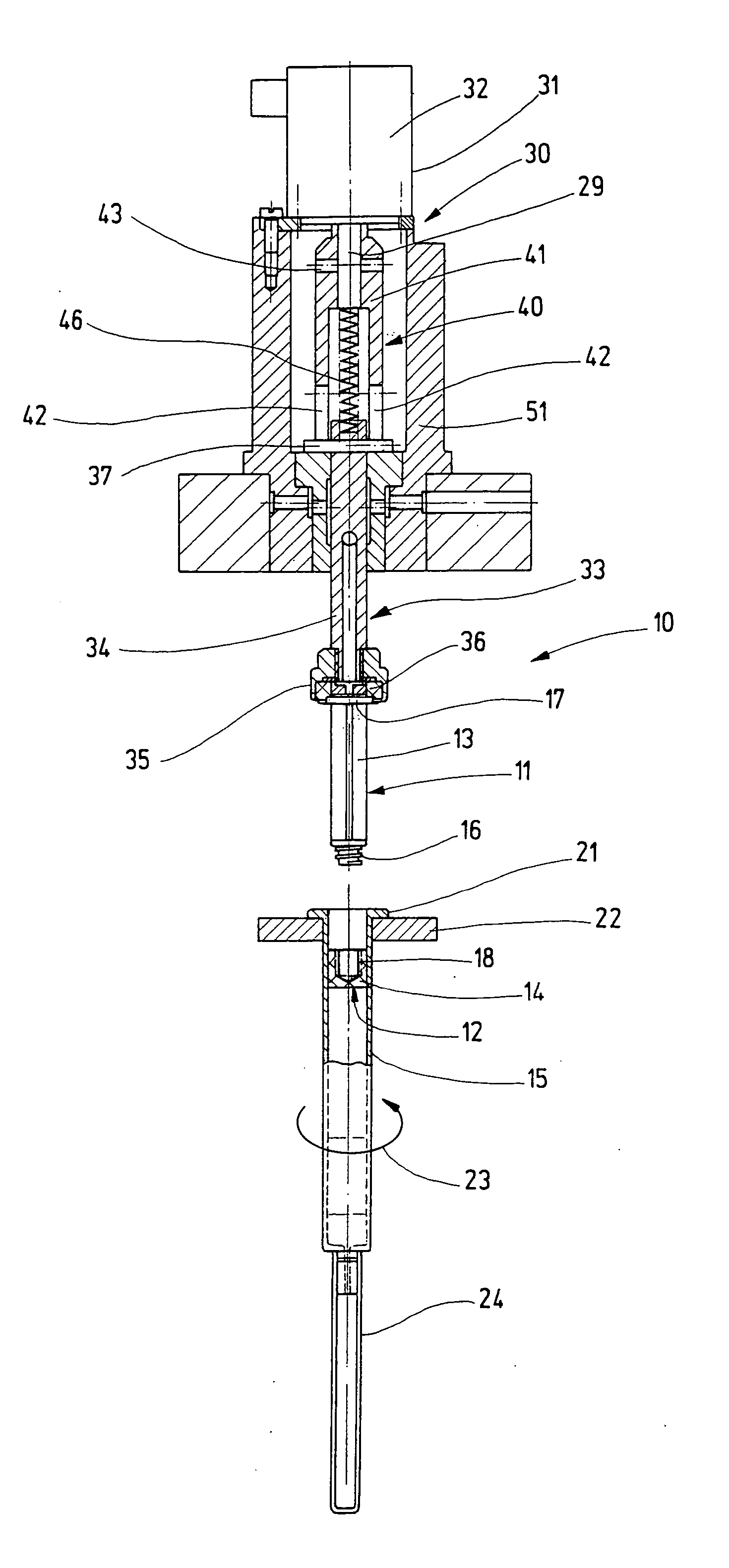
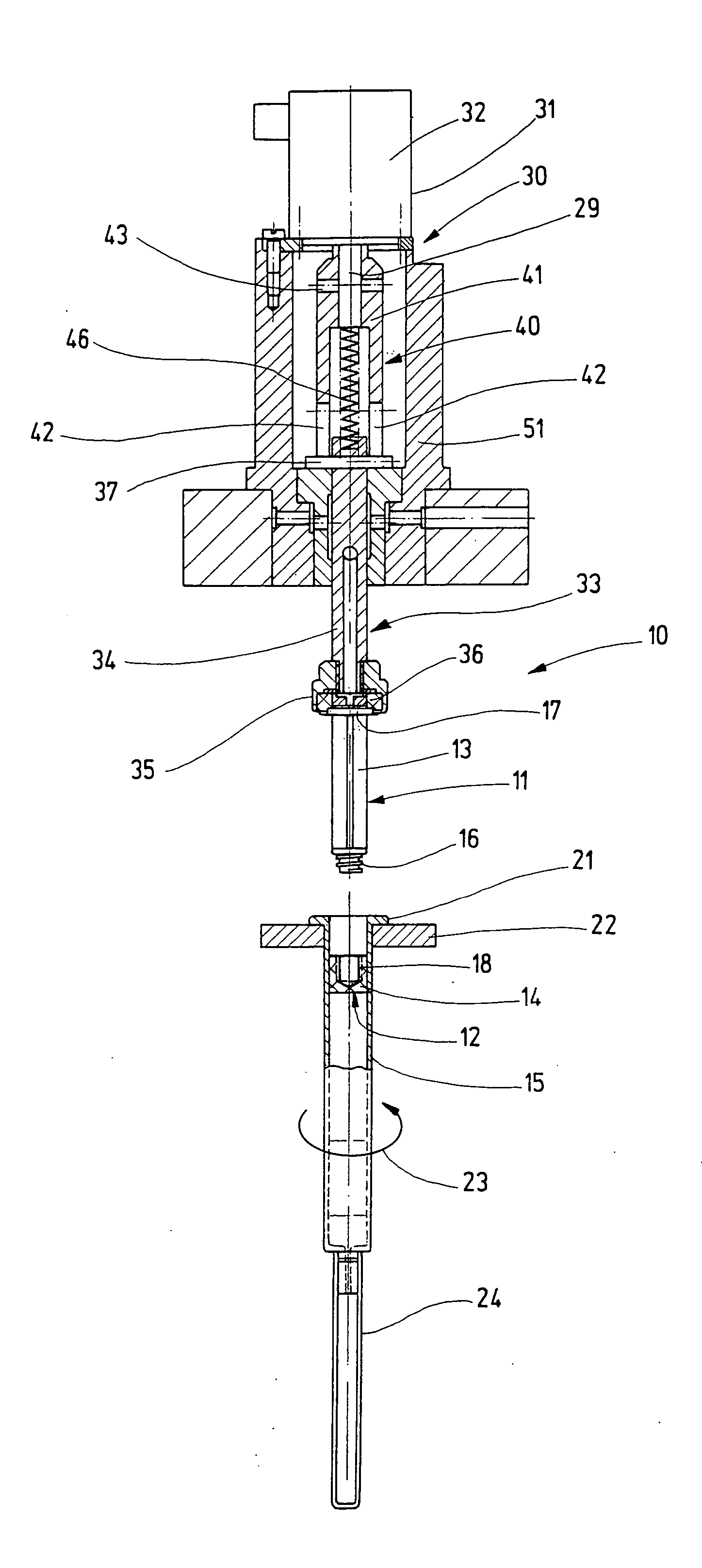
[0013] A holding device in accordance with the present invention is shown with elements which are necessary for this case and identified as a whole with reference numeral 10. The holding device 10 allows to limit a moment for objects 11 which are screwed in components 12.

[0014] In the shown embodiment the holding device 10 is a part of a not shown apparatus for filling and assembling an of syringes. The holding device 10 has for example twelve such devices which are arranged on a continuously operating piston rod charging apparatus. In this apparatus as the objects 11, piston rods 13 of the syringes are provided and they must be screwed in the pistons 14 as the components.

[0015] The pistons 14 are located inside the syringe cylinder 15 and held on the inner wall of the syringe cylinders 15 by static friction. The piston rod 13 has a lower threaded portion 16, and on the opposite end it has a finger support 17, which here for example is circular and is a component of the piston rod...


PUM


Abstract

A holding device with limitation of a moment for objects formed as piston rods to be screwed into components formed as pistons contained in an interior of syringe cylinders, the holding device comprising a holder for an object; a braking device which is formed to non-rotatably hold the holder and, through the holder, the object with a predetermined braking moment, the braking device having an electric brake which acts on the holder.

Description

BACKGROUND OF THE INVENTION [0001] The present invention relates to a holding device with moment limiting means for objects which are to be screwed into components. [0002] Such screwing-in problems take place in many areas, where holding devices are used with limitations of moments. An example of such use is the filling and assembly of medical syringes. Devices are provided for this purpose, in which the individual working steps are performed in an automatic process, for example the filling of the syringe cylinder, subsequently the insertion of the piston in the filled syringe cylinder, and thereafter the screwing of the piston rod into the piston. The pistons are generally composed of synthetic plastic, rubber or similar easily deformable materials. [0003] A holding device of the above mentioned general type is disclosed for example in the German patent document DE 91 08 831. This device has a braking unit with a braking member located on a holder. During turning in, it is brought ...

Claims


Application Information

Patent Timeline
Patent Type & Authority Applications(United States)
IPC IPC(8): A61M5/315B23P19/06B25B23/14
CPCB25B23/14B23P19/066
Inventor NEBER, FRITZ
Owner GRONINGER
Learn More