Demodulator and data recorder containing same

a demodulator and data recorder technology, applied in the field of demodulator and data recorder containing same, can solve the problems of waveform collapse, noise may be superimposed on the wobble signal, and errors may easily take place in judgment, so as to suppress the increase of demodulation errors and few errors

Inactive Publication Date: 2005-04-21
TEXAS INSTR INC
View PDF8 Cites 16 Cited by
  • Summary
  • Abstract
  • Description
  • Claims
  • Application Information

AI Technical Summary

Benefits of technology

[0027] The demodulator of various aspects of the present invention makes it possible to suppress increases in the demodulation error when the waveform of the phase modulated signal collapses due to the superimposition of noise in the signal. Also, even when the waveform of the phase modulated signal pre-recorded in the recording medium collapses due to an increased number of rewrite cycles, it still may be possible with the data recorder of the present invention, to write high-quality data with few errors to the recording medium.

Problems solved by technology

However, when a repeated write operation is performed on a rewritable optical disk, such as a DVD+RW, etc., due to the degradation of the optical disk, noise may be superimposed on the wobble signal.
Consequently, when noise is superimposed on the phase modulated signal, the waveform collapses, and errors may easily take place in the judgment, which is undesirable.
However, the aforementioned synchronization detection method requires complicated multiplication of sinusoidal waveforms.
Consequently, it is difficult to increase the processing speed, which is undesirable.
Consequently, the circuit scale and power consumption increase, which is also undesirable.

Method used


Image

  • Demodulator and data recorder containing same
  • Demodulator and data recorder containing same
  • Demodulator and data recorder containing same

Examples


Embodiment Construction

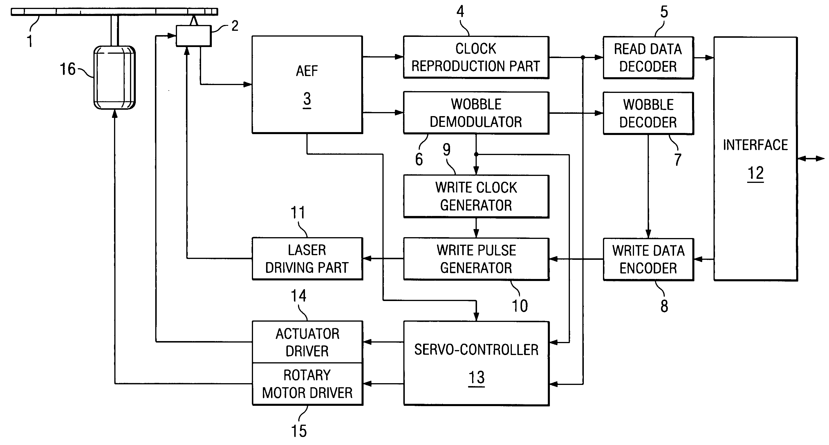
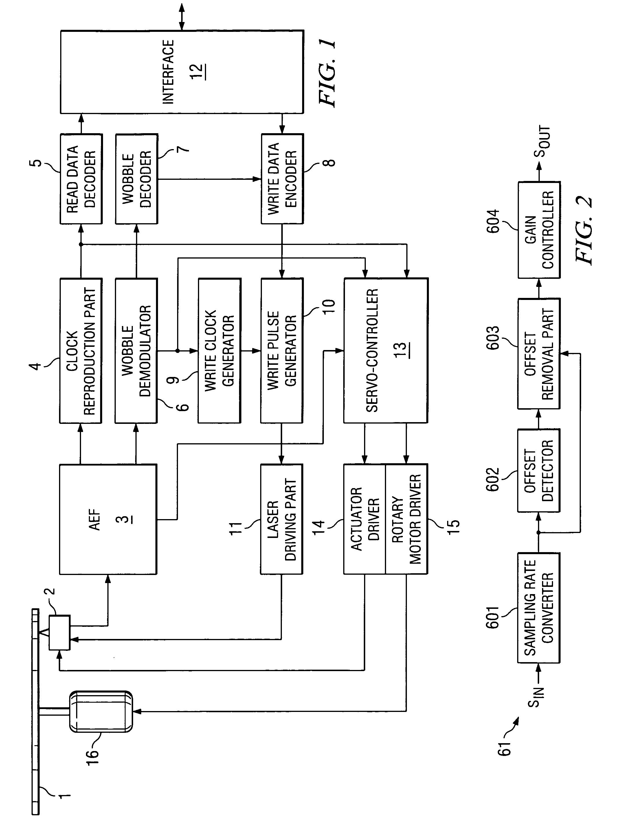
[0035]FIG. 1 is a block diagram illustrating an example of constitution of the data recording / reproduction device pertaining to an embodiment of the present invention.

[0036] The data recording / reproduction device shown as example in FIG. 1 has the following parts: optical pickup 2, analog front end part 3, clock reproduction part 4, read data decoding part 5, wobble demodulator 6, wobble decoding part 7, write data encoding part 8, write clock generating part 9, write pulse generating part 10, laser driving part 11, interface part 12, servo-controller 13, actuator driving part 14, rotary motor driver 15, and disk motor 16. Also, wobble demodulator 6 as an embodiment of the demodulator of the present invention.

Optical Pickup 2

[0037] In optical pickup 2, when data written in optical disk 1 is read, a laser beam for data read and for generating control signal is irradiated on the recording surface of optical disk 1, and the light reflected from the recording surface is converted into...


PUM

PropertyMeasurementUnit
phaseaaaaaaaaaa
thresholdaaaaaaaaaa
phase modulatedaaaaaaaaaa

Abstract

A demodulator for wobble signals or other phase-modulated signals that can reduce demodulation errors due to superimposition of noise, as well as a data recording / reproduction device that contains said demodulator. In the signal range of the bit signal obtained by insertion synchronously with detected bit synchronization signal Bsync, prescribed sign operations are performed on integration values S2 of the wobble signals during periods where phase changes of bit signals should take place, respectively, and the results are summed so as to compute characteristic quantities S13 and S16 of the bit signals “1” and “0,” respectively. On the basis of the result of the comparison of the characteristic quantities, the value of the bit signal corresponding to bit synchronization signal Bsync is determined.

Description

FIELD OF THE INVENTION [0001] The present invention pertains to a demodulator for a phase modulated signal and a data recorder containing said demodulator. For example, the present invention pertains to a demodulator for demodulating the wobble signal of an optical disk and a data recorder for said optical disk. BACKGROUND OF THE INVENTION [0002] In general, the recording surface of a recordable optical disk contains a pre-formed guide groove in the shape of a spiral to ensure that the laser beam can correctly follow the recording track during writing. The edges of the guide groove describe a periodic undulation or wobble. As the laser beam is irradiated on the edges, the reflected light is converted into an electronic signal, so that a periodic signal (wobble signal) corresponding to the wobble is obtained. [0003] For example, when the optical disk is rotated at a constant linear velocity, the write signal may be used as the control signal. On the other hand, when the optical disk ...

Claims


Application Information

Patent Timeline
Patent Type & Authority Applications(United States)
IPC IPC(8): H02J7/00G11B7/005G11B20/10G11B20/14G11B27/24H01M10/44H04L27/22
CPCG11B7/0053G11B20/10009G11B2220/2562G11B27/24G11B2220/216G11B20/1403Y02E60/10H01M10/441H02J7/0016H02J7/00302H02J7/00306H02J7/00308
Inventor SHIGEEDA, AKIOOHMARU, MAKOTO
Owner TEXAS INSTR INC
Why Eureka
Try Eureka