Movement detection method and a mobile terminal

a detection method and mobile terminal technology, applied in multiplex communication, data switching networks, wireless commuication services, etc., can solve the problems of difficult to estimate the time necessary, the handover time is made longer, and the possibility of producing a movement detection delay of 500 ms at most and a few hundred ms, so as to reduce the time of handover

Inactive Publication Date: 2005-04-21
PANASONIC CORP
View PDF3 Cites 52 Cited by
  • Summary
  • Abstract
  • Description
  • Claims
  • Application Information

AI Technical Summary

Benefits of technology

[0042] By virtue of the features as described, even in a usage state where radio communication is performed between the mobile terminal and the router, the time of handover can be reduced according to the present invention as far as communication with the mobile terminal is made at the same frequency both by a prior-to-movement router and a movement destination router.

Problems solved by technology

As a result there is a possibility to produce a movement detection delay of 500 ms at most and of a few hundred ms on average.
That is to say, because there is an occurrence of at least the above-described waiting time after the Layer 2 connection until the formation of an IP address, handover time is made longer while it is difficult to estimate the time necessary for performing the handover.
This will lead to the loss of application resource.
For example, in the case of determining the buffer size of application data in accordance with the handover time, it is required to ensure the size enabling to accommodate the maximum amount of packets received within 500 ms but there is rare chance to actually consume all the buffer size, which is a loss of the data buffer resources.
Meanwhile, in the second implementation method of Fast Mobile IP that is described in “Fast Handover for Mobile IPv6” IETF Mobile IP WG Internet-Draft, there is a necessity to prepare two radio interfaces that leads to a problem of increasing circuits and consumption power.
In such a case, it is made impossible to notify the information of the movement destination access router to the prior-to-movement access router (S2016), unable to establish a tunnel between the access router 100c and the access router 100d, thus generating a packet loss.

Method used


Image

  • Movement detection method and a mobile terminal
  • Movement detection method and a mobile terminal
  • Movement detection method and a mobile terminal

Examples


1st exemplary embodiment

[0057] The first exemplary embodiment of the present invention is demonstrated hereinafter with reference to FIGS. 1, 2, 4 and 6.

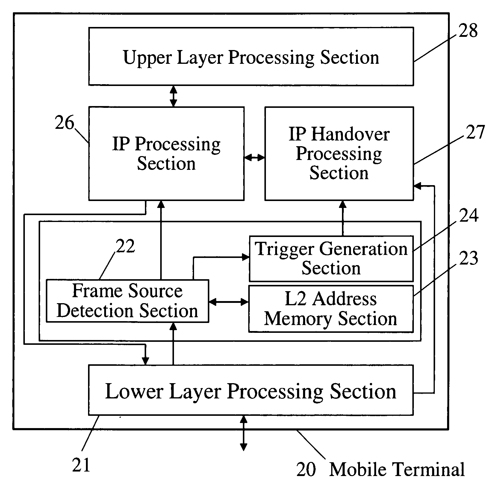
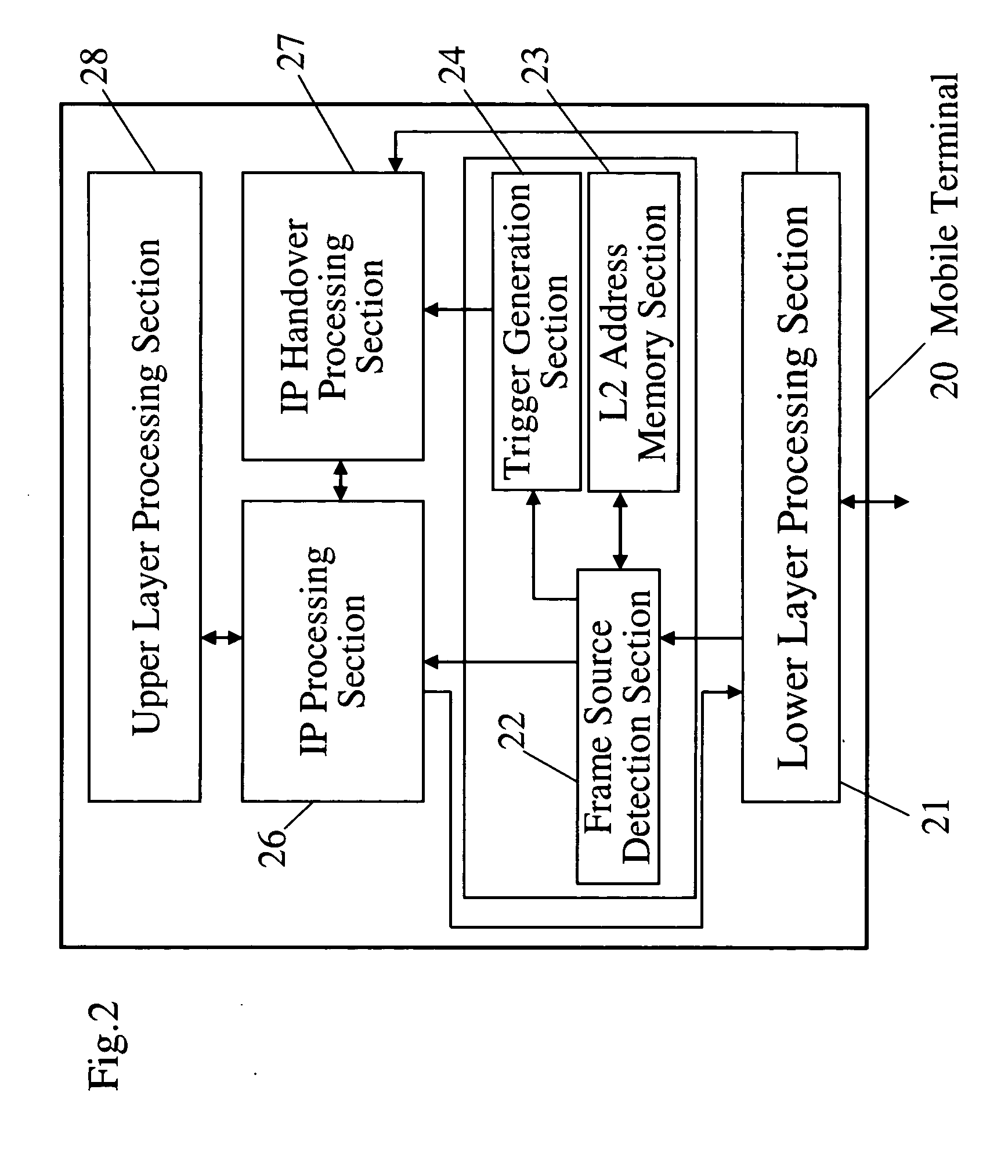
[0058] The first exemplary embodiment of the present invention is, in the case where neighbor access routers provide radio access service at the same frequency, that a mobile terminal 20, when moving, generates a movement detection trigger in reaction to receiving a L2 frame from an access router that is different from the currently connected access router to initiate a part of the IP handover processing.

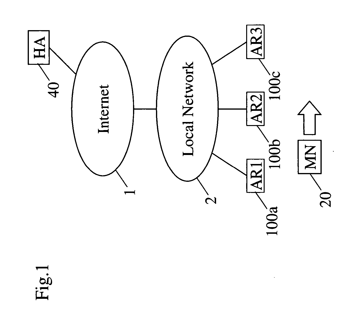
[0059]FIG. 1 is a block diagram of a mobile communication system according to the present invention.

[0060] In FIG. 1, a local network 2 connects to the internet 2, access router devices 100a to 100c connect to the local network (AR1 to AR3), a mobile terminal (MN) 20 moves while being connected to the access router device 100, and a home agent (HA) 40 houses the mobile terminal 20.

[0061] In the mobile communication system as shown in FIG. 1, the mobile...


PUM


Abstract

In accordance with a movement detection method, a mobile terminal in moving among access router devices all set at the same frequency, stores the link layer address of the currently reachable access router device. When receiving a Layer 2 frame from a new access router device, the mobile terminal issues a trigger for requesting to implement a part of IP handover processing. By so doing, it allows IP handover processing to be initiated at higher speed than in the case of the conventional IP layer, thus enabling to reduce the total time of handover processing.

Description

FIELD OF THE INVENTION [0001] The present invention relates to a method of movement detection of a mobile terminal implementing an internet protocol and further an IP mobility procedure like as Mobile IP. BACKGROUND OF THE INVENTION [0002] There is a Mobile IP as one of movement controlling methods in the internet system, where Mobile IPv4 corresponding to IPv4 is standardized by RFC3220 (IP Mobility Support). Besides, Mobile IPv6 corresponding to IPv6 is in process of standardization by the Internet-Draft “draft-ietf-mobileip-ipv6 (Mobility Support in IPv6)” even now. Thanks to these protocols, it is made possible to continue the communication with the use of the same address if a mobile terminal moves between different networks. In Mobile IP, the mobile terminal will, when it is away from the home link, form a care-of address to be temporarily used on the link by obtaining prefix information of the currently connected link from the network information that is transmitted from the ...

Claims


Application Information

Patent Timeline
Patent Type & Authority Applications(United States)
IPC IPC(8): H04L12/28H04L12/701H04B7/26H04L29/06H04L29/12H04W36/00H04W36/12H04W36/32H04W36/36H04W40/02H04W40/34H04W80/00H04W80/04H04W88/18
CPCH04L29/12009H04L29/12018H04L61/10H04W36/0011H04W88/18H04W36/32H04W40/02H04W80/00H04W36/12H04L61/00
Inventor IKEDA, SHINKICHIFUNABIKI, MAKOTO
Owner PANASONIC CORP
Why Eureka
Try Eureka