Pneumatic device and lithographic device

A pneumatic device and pneumatic control technology, applied in the field of lithography machines, can solve the problems such as the large volume of the pneumatic device and the inability to set a position close to the silicon wafer in the lithography equipment.

Active Publication Date: 2020-01-14
SHANGHAI MICRO ELECTRONICS EQUIP (GRP) CO LTD
View PDF7 Cites 0 Cited by
  • Summary
  • Abstract
  • Description
  • Claims
  • Application Information

AI Technical Summary

Problems solved by technology

[0003] At present, in order to improve the yield of lithography equipment and reduce the vacuum stabilization time, the pneumatic device is preferably arranged in the position close to the silicon wafer in the lithography equipment, but the existing pneumatic device includes at least 4 miniature solenoid valves, and the lithography The space near the equipment to the silicon wafer is very compact, resulting in the large size of the existing pneumatic device, which cannot be installed in the lithography equipment very close to the silicon wafer

Method used


Image

  • Pneumatic device and lithographic device
  • Pneumatic device and lithographic device
  • Pneumatic device and lithographic device

Examples


Embodiment 1

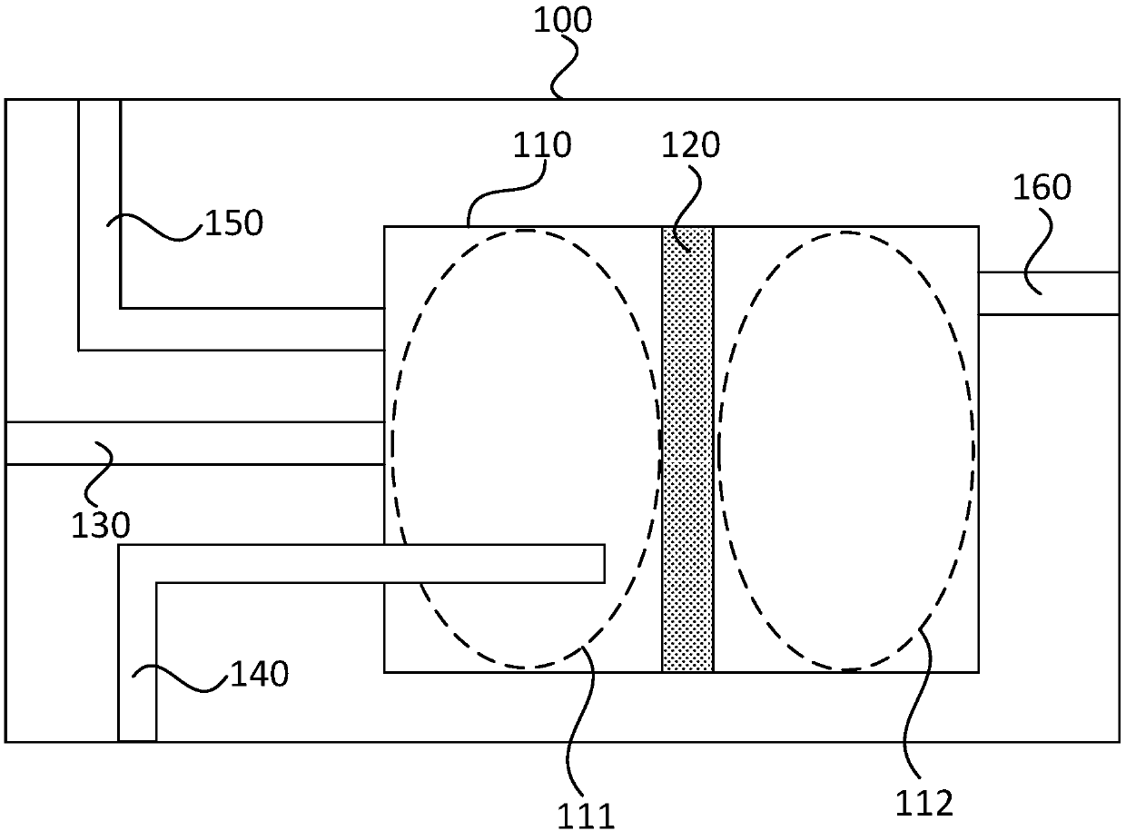
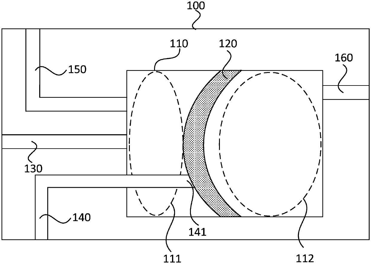
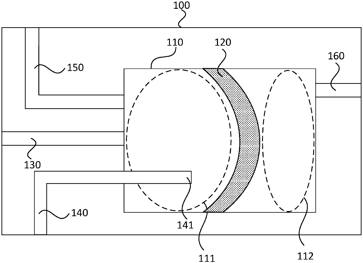
[0048] figure 1 For the sectional view of the pneumatic device provided by Embodiment 1 of the present invention, see figure 1, the pneumatic device includes an air control block 100 and an air control passage 130, and the air control block 100 is provided with a gas switching chamber 110, a flexible sheet 120, an atmospheric pipeline 140, a first vacuum branch 150 and a second vacuum branch 160, The two ends of the gas control channel 130 are respectively connected with the gas switching chamber 110 and the object to be controlled ( figure 1 not shown) connected. The gas switching chamber 110 is sealed, and the flexible sheet 120 is arranged in the gas switching chamber 110, and is used to divide the gas switching chamber 110 into a first isolation area 111 and a second isolation area 112, which are isolated from each other. The first isolation area 111 It is always connected with the first vacuum branch 150 and the air control passage 130, and the second isolation area 112...

Embodiment 2

[0055] Figure 4 For the sectional view of the pneumatic device provided by Embodiment 2 of the present invention, see Figure 4 On the basis of the first embodiment, optionally, the air control block 100 of the pneumatic device is formed by splicing the first flow distribution block 210 and the second flow distribution block 220; One side of the two diversion block 220, the second isolation area 112 is set on the side of the second diversion block 220 facing the first diversion block 111, after the first diversion block 210 and the second diversion block 220 are spliced, the first isolation area 111 and The second isolation area 112 forms the gas switching chamber 110 , and the flexible sheet 120 is located at the junction of the first flow distribution block 210 and the second flow distribution block 220 , serving as sealing surfaces of the first isolation area 111 and the second isolation area 112 respectively.

[0056] Wherein, a plurality of gas paths may be provided in ...

Embodiment 3

[0083] Figure 7 For the sectional view of the pneumatic device provided by Embodiment 3 of the present invention, see Figure 7 , on the basis of Embodiment 1, optionally, the second vacuum branch 160 includes a first sub-branch 161 and a second sub-branch 162, the output end of the first sub-branch 161 is vertical to the flexible sheet 120 The projection is located between the first protrusion 121 and the annular protrusion 122 , and the vertical projection of the output end of the second sub-branch 162 on the flexible sheet 120 is located in the first protrusion 121 .

[0084] When the first solenoid valve 230 switches the first vacuum branch 150 to conduction, the first vacuum branch 150 is evacuated, and the flexible sheet 120 is moved to the top 113 of the gas switching chamber 110 by the vacuum of the first vacuum branch 150 Bending deformation, the flexible sheet 120 is in close contact with the end of the isolation pipeline 240, the inner space 1111 is isolated from ...


PUM

PropertyMeasurementUnit
thicknessaaaaaaaaaa
thicknessaaaaaaaaaa
diameteraaaaaaaaaa

Abstract

The embodiment of the invention provides a pneumatic device and a lithographic device. The pneumatic device includes a gas control block and a gas control path. A gas switching chamber, a flexible sheet, an air pipeline, a first vacuum branch and a second vacuum branch are arranged inside the gas control block. Two ends of the gas control path are communicated with the gas switching chamber and anobject to be controlled respectively. The gas switching chamber is sealed. The flexible sheet is arranged in the gas switching chamber to separate the gas switching chamber into a first isolation zone and a second isolation zone, which are isolated from each other. When the first vacuum branch is evacuated, the air control path guides the vacuum input by the first vacuum branch to the object to be controlled to realize adsorption. When the second vacuum branch is evacuated, the air control path guides the air input from the air pipeline to the object to be controlled to realize release. According to the invention, the volume of the pneumatic device is reduced, so that the pneumatic device can be set at a position close to a silicon wafer in the lithographic device; the silicon wafer transfer time is reduced; and the exposure efficiency is improved.

Description

technical field [0001] The invention relates to the field of photolithography machines, in particular to a pneumatic device and a photolithography device. Background technique [0002] In semiconductor lithography equipment, the pneumatic device is an extremely important subsystem for completing the handover of silicon wafers. The speed of silicon wafer handover directly affects the productivity of lithography equipment. The pneumatic device is mainly to input the gas source through the solenoid valve to achieve the rapid switching between the vacuum and the ambient atmosphere in the process of continuously switching silicon wafers. [0003] At present, in order to improve the yield of lithography equipment and reduce the vacuum stabilization time, the pneumatic device is preferably arranged in the position close to the silicon wafer in the lithography equipment, but the existing pneumatic device includes at least 4 miniature solenoid valves, and the lithography The space n...

Claims


Application Information

Patent Timeline
Patent Type & Authority Applications(China)
IPC IPC(8): G03F7/20
CPCG03F7/70858G03F7/70991
Inventor 赵文波胡小林张丽
Owner SHANGHAI MICRO ELECTRONICS EQUIP (GRP) CO LTD
Why Eureka
Try Eureka