
Combination distraction dental implant and method of use

Inactive Publication Date: 2005-04-21
STUCKI MCCORMICK SUZANNE
View PDF10 Cites 20 Cited by
  • Summary
  • Abstract
  • Description
  • Claims
  • Application Information

AI Technical Summary

Benefits of technology

[0040] It is accordingly one object of the present application to provide a new combination dental implant and distraction device and method of using which limits the number of surgical procedures a patient must undergo to have an optimum dental implant placed in an area having initially insufficient bone stock.
[0043] Another object of the invention is to provide a combination distraction dental implant that eliminates the need for the complete removal of the distraction device prior to placement of a separate dental implant during another surgical procedure.
[0044] A further object of the present invention is to provide a combination distraction dental implant that eliminates the need for bone grafts in areas of limited bone stock in order to place optimal dental implants.
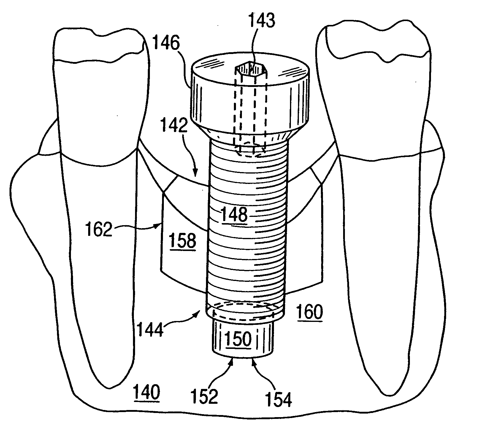
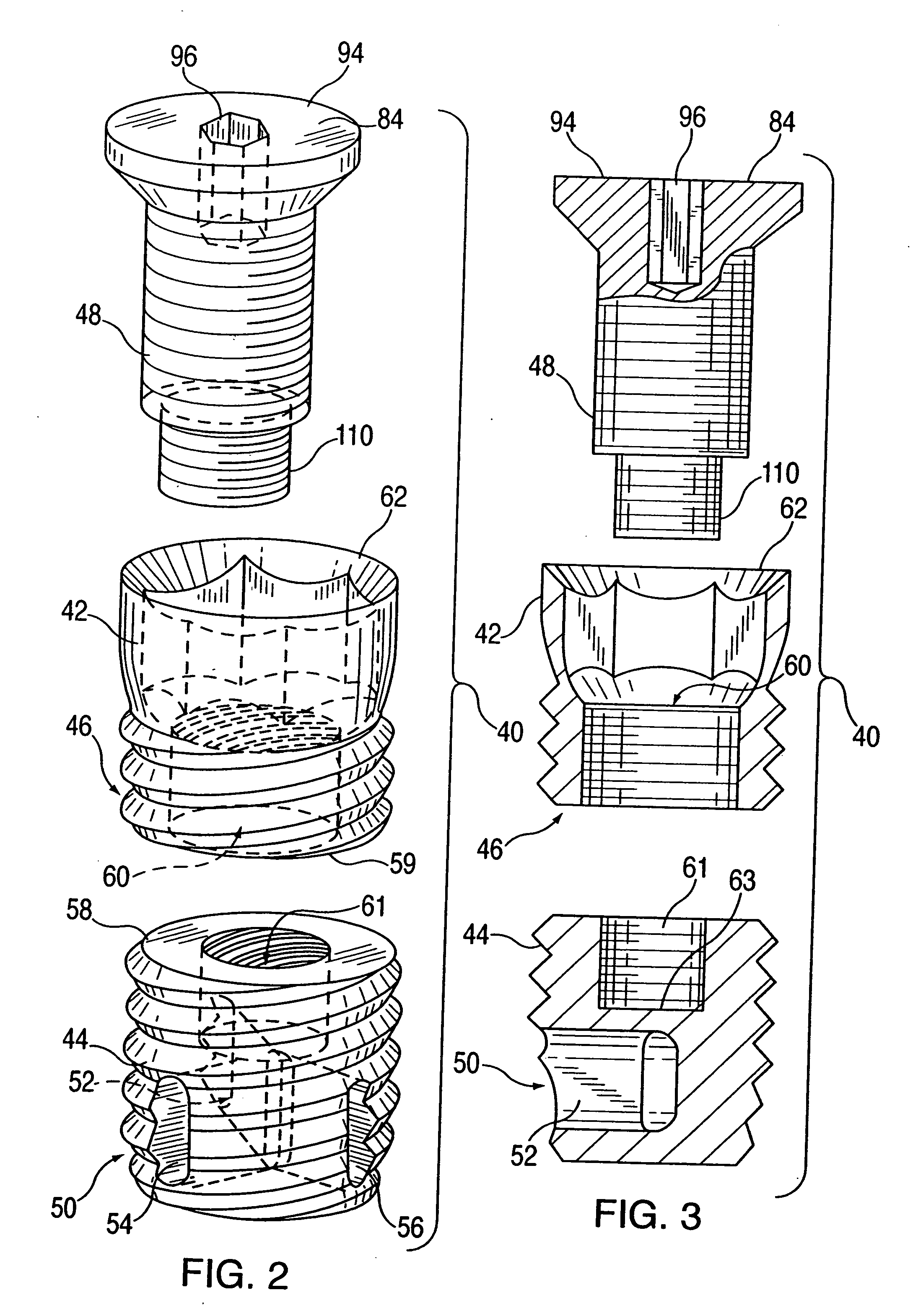
[0049] One representative method of the present invention includes the steps of: providing a three component distraction device including a hollow coronal component, a partially hollow apical component and a linking component or a first expansion component; placing the combination distraction device in a predetermined site where bone regeneration is required; allowing the combination distraction device to become integrated into the bone; ensuring that osseous incorporation of the combination distraction device into the bone has been accomplished; performing a corticotomy in the buccal bone at the level of the contiguous surfaces of two of the three components of the combination distraction device to form a distraction gap; educating the patient as to the care and activation of the three component combination distraction device; after allowing for a period of initial healing, maneuvering the connecting component thereby separating the coronal component and the apical component to widen the distraction gap in the bone.
[0050] Another representative embodiment of a more general purpose distraction device of the present invention includes: a first component selectively operatively removably connectable to a first predetermined portion of a bone; a second component selectively operatively removably connectable to a second predetermined portion of the bone, the second component being operatively positioned proximal the first component; and a connecting component for: (a) operatively connecting the first and the second components, and (b) controllably expanding the distance between the first and the second components.

Problems solved by technology

Thus, further turning of the combined dental implant / distractor cannot cause it to move further in a vertical direction.
Premature tooth loss can limit a patient's ability to chew and speak clearly.
These two prior methods served only to fill the void of the edentulous space by replacing the crown of the involved teeth but did not replace the root.
However, as a consequence of premature tooth loss, patients have lost bone in the area of a proposed implant.
This bone loss has, in some cases, limited the surgical options, requiring the dentist to place a smaller than optimal sized dental implant.
If the dental implant is too small to accommodate the mechanical load from chewing, with time, it will loosen and fail.
Additionally, due to bone loss or insufficient bone in the implant area, the dental implant may be placed in an anatomical location where the existing bone may not be ideal for prosthetic reconstruction with a crown or bridge, forcing the dentist to replace the missing tooth with a crown that is not as aesthetic or functional as would be considered optimal.
Regardless of the technique and materials used, the potential morbidity to the patient can be significant.
This results in creation of new bone in the expansion gap.
This phenomenon of recreating the same size and shape as the original bone is unique to bone generation using distraction osteogenesis and is not accomplished with conventional bone transplantation.
The current external and submerged distraction devices are also limited in the amount of bone expansion each device can deliver because they have fixed internal mechanisms which provide for bone expansion from 0.0 mm to the full length specified for a particular device.
Devices which are located externally function well but can pose aesthetic concerns while the patient is utilizing the device and also facial scars are created as the pins holding the device in place are moved as the device is activated and the bone is expanded.
Intraoral devices do not have as many aesthetic concerns, but are bulky, displacing the lips and cheeks, which can give the patient the appearance of a local infection.
Consequently, variations in the basic design of root form dental implants is limited.
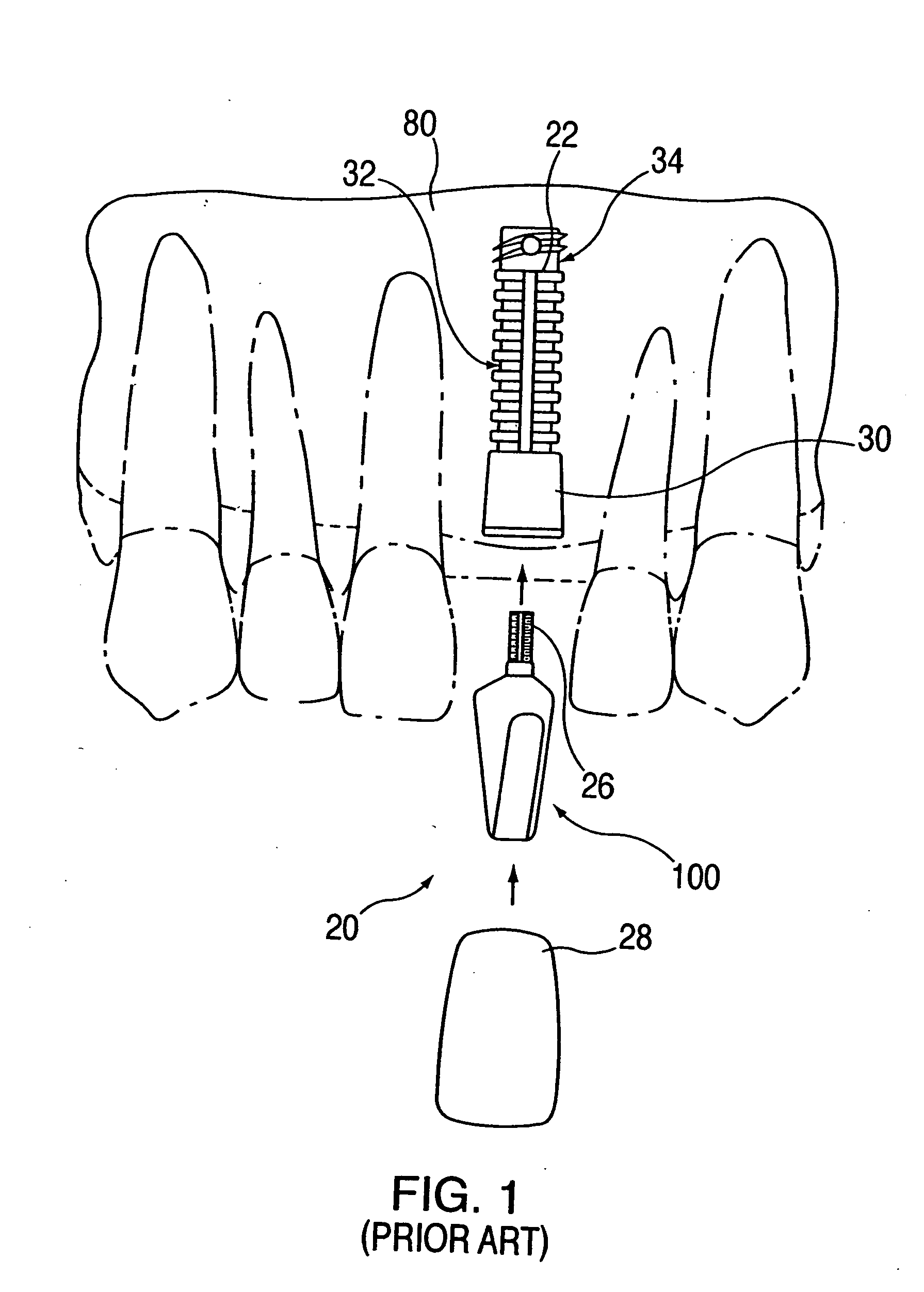
However, since the new bone is still relatively weak and incompletely ossified, a period of about four to about six weeks is required before the fabrication and installation of the final prosthesis such as, for example, a crown 28, a bridge or dentures.

Method used


Image

  • Combination distraction dental implant and method of use
  • Combination distraction dental implant and method of use
  • Combination distraction dental implant and method of use

Examples


Embodiment Construction

[0067] The science and technology of dental implants have been described above. As such, dental implants have evolved from a simple cylindrical form to now having external threads, self tapping grooves, vertical grooves, vents, apical holes and treads, and surface coatings / treatments (titanium plasma spray, acid-etch, hydroxylapatite, microspheres, sintered pores, bone promoting substances, selective surface combinations), etc., all of which act to serve as mechanisms to facilitate placement and promote bone healing, thus increasing retention of the implant within the bone. As is known, dental implants can be made of various grades of titanium (Grade I-IV) to increase the strength of the implant itself. Implants may also be stepped or tapered apically, allowing for placement into narrow anatomical spaces. Implants may have a smooth collar to provide for cervical healing. Implants may have external or internal hexagonal, octagonal, spline and other designs to allow for increased rete...


PUM


Abstract

A combination dental implant / prosthetic support and distractor for facilitating distraction osteogenesis comprises a basically cylindrical shaft having a set of threads on the outside surface and a smooth, distal tip which bears against the bone of the jaw of the patient. Rotation of the device in the mouth of the patient, after a suitable surgical cut is made, causes the adjacent tissue to move or ride up the screw threads to create space between the cut jaw segment and the balance of the jaw tissue. This space is then filled in by distraction osteogenesis. The implant / distractor is left in-situ, after the distraction is finished, for securement thereto of a dental prosthetic, either a bridge or crown. In an embodiment of the invention, a flat disc is placed in the blind bore drilled into the jaw such that the distal tip of the shaft of the combined implant / distractor, will bear against it. A protective cap and / or collar can be provided, suitable shaped, to protect the shaft / gum line from bacterial attack. Also, the shaft may be provided with an internal passageway and one or more radially extending branches. Growth-enhancing material can be passed through the passageway and branches to promote bone development and recovery. In another embodiment, a coronal member is provided, extra-osseously, to facilitate the distraction osteogenesis process. In one version of the device, fluting is provided to the exterior surface of the shaft so that bone growth is enhanced at that intersection. Also, the shaft can be provided with a flat disc at its head to reduce rocking of the device in the mouth.

Description

[0001] This invention is a continuation-in-part of my prior patent application Ser. No. 08 / 886,078 filed Jul. 2, 1997 entitled Combination Distraction Dental Implant and Method of Use. That application which is reproduced in its entirety hereinafter is directed to an in situ combination distraction and dental implant system comprising an apical member having a top surface, a coronal member comprising internal threads and a bottom surface with the bottom surface of the coronal member facing the top surface of the apical member and a rod like connecting distraction member comprising a first set of external threads matingly engageable with the internal threads of the coronal member facilitating mechanical incremental rotation of the connection and distraction member with respect to the coronal member such that incremental rotation of the connecting and distraction member causes the coronal member to vertically separate from the apical member and create a correspondingly sized vertical ...

Claims


Application Information

Patent Timeline
IPC IPC(8): A61B17/66A61C8/00
CPCA61B17/663A61B17/666A61C8/0018A61B17/8685A61C8/0006A61B17/864
Inventor STUCKI-MCCORMICK, SUZANNE
Owner STUCKI MCCORMICK SUZANNE
Learn More