Moisture transport system for contact electrocoagulation

a technology of moisture transport system and electrocoagulation, which is applied in the field of apparatus and methods for ablating or coagulating the interior surfaces of body organs, can solve the problems of ineffective heating process, inability to account for factors, and inability to achieve the ablation depth and ablation profile of such devices,

Inactive Publication Date: 2005-04-21
CYTYC SURGICAL PRODS
View PDF99 Cites 87 Cited by
  • Summary
  • Abstract
  • Description
  • Claims
  • Application Information

AI Technical Summary

Problems solved by technology

However, because no data or feedback is available to guide the physician as to how deep the tissue ablation has progressed, controlling the ablation depth and ablation profile with such devices can only be done by assumption.
For example, the heated fluid method is a very passive and ineffective heating process which relies on the heat conductivity of the tissue.
This process does not account for variations in factors such as the amount of contact between the balloon and the underlying tissue, or cooling effects such as those of blood circulating through the organ.
RF ablation techniques can achieve more effective ablation since it relies on active heating of the tissue using RF energy, but presently the depth of ablation using RF techniques can only be estimated by the physician since no feedback can be provided as to actual ablation depth.
Because ablation is carried out within a closed cavity within the body, the steam cannot escape and may instead force itself deeply into the tissue, or it may pass into areas adjacent to the area intended to be ablated, causing embolism or unintended burning.
Another problem with prior art ablation devices is that it is difficult for a physician to find out when ablation has been carried out to a desired depth within the tissue.
Thus, it is often the case that too much or too little tissue may be ablated during an ablation procedure.

Method used


Image

  • Moisture transport system for contact electrocoagulation
  • Moisture transport system for contact electrocoagulation
  • Moisture transport system for contact electrocoagulation

Examples


first exemplary embodiment

[0054] Structure

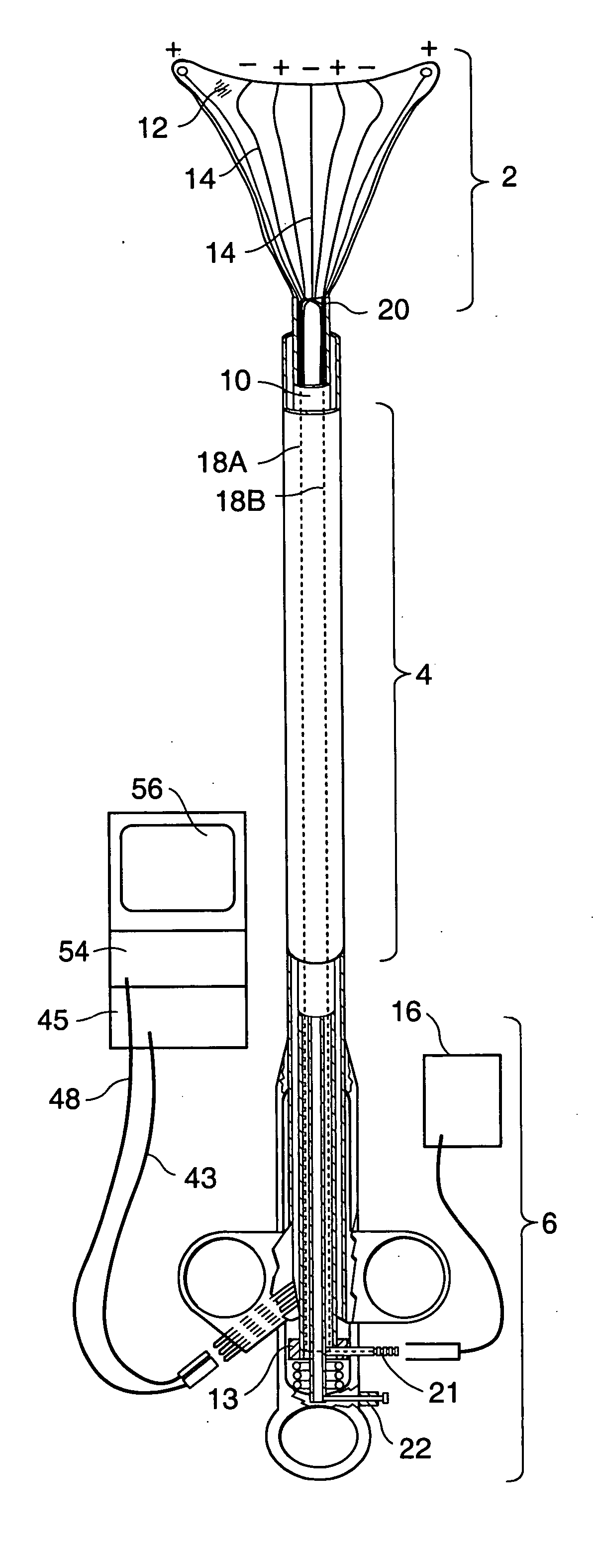
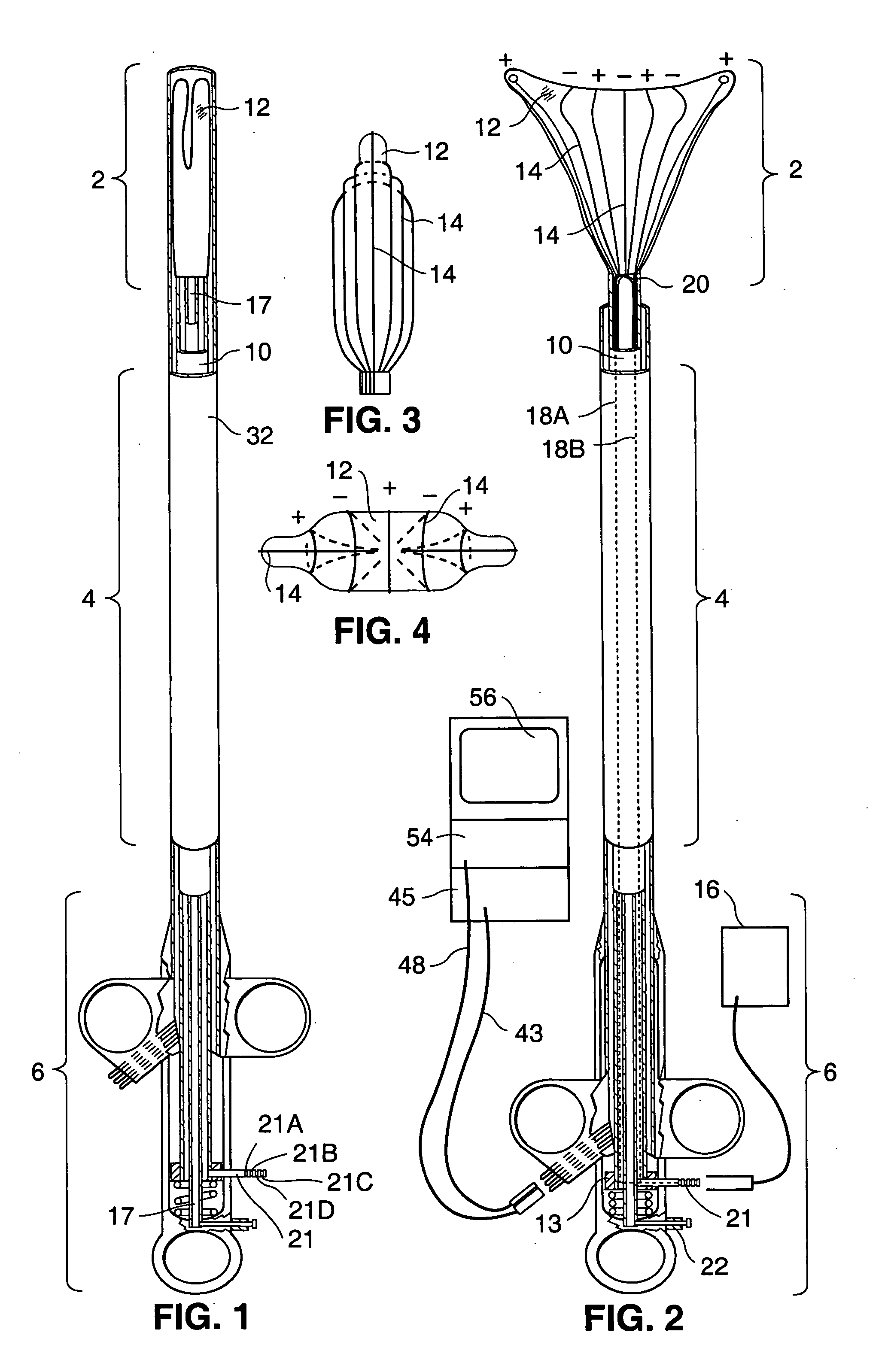
[0055] Referring to FIGS. 1 and 2, an ablation device according to the present invention is comprised generally of three major components: RF applicator head 2, main body 4, and handle 6. Main body 4 includes a shaft 10. The RF applicator head 2 includes an electrode carrying means 12 mounted to the distal end of the shaft 10 and an array of electrodes 14 formed on the surface of the electrode carrying means 12. An RF generator 16 is electrically connected to the electrodes 14 to provide mono-polar or bipolar RF energy to them.

[0056] Shaft 10 is an elongate member having a hollow interior. Shaft 10 is preferably 12 inches long and has a preferred cross-sectional diameter of approximately 4 mm. A collar 13 is formed on the exterior of the shaft 10 at the proximal end. As best shown in FIGS. 6 and 7, passive spring member 15 are attached to the distal end of the shaft 10.

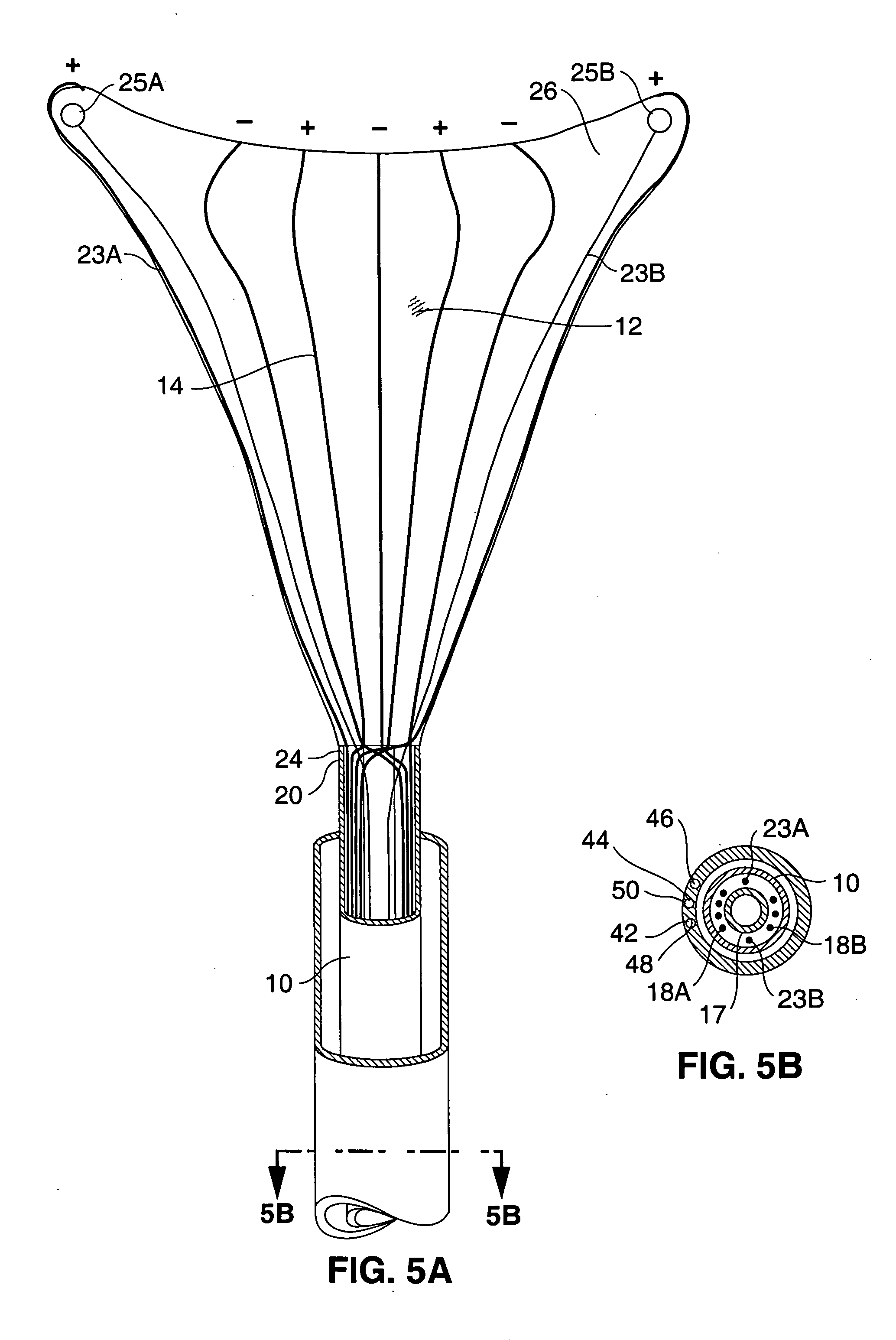
[0057] Extending through the shaft 10 is a suction / insufflation tube 17 (FIGS. 6-9) having a plur...

second exemplary embodiment

[0106] Structure

[0107] A second embodiment of an ablation device 100 in accordance with the present invention is shown in FIGS. 21-37B. The second embodiment differs from the first embodiment primarily in its electrode pattern and in the mechanism used to deploy the electrode applicator head or array. Naturally, aspects of the first and second exemplary embodiments and their methods of operation may be combined without departing from the scope of the present invention.

[0108] Referring to FIGS. 21 and 22, the second embodiment includes an RF applicator head 102, a sheath 104, and a handle 106. As with the first embodiment, the applicator head 102 is slidably disposed within the sheath 104 (FIG. 21) during insertion of the device into the uterine cavity, and the handle 106 is subsequently manipulated to cause the applicator head 102 to extend from the distal end of the sheath 104 (FIG. 22) and to expand into contact with body tissue (FIG. 33).

[0109] RF Applicator Head

[0110] Referri...


PUM


Abstract

An apparatus and method for use in performing ablation or coagulation of organs and other tissue includes a metallized fabric electrode array which is substantially absorbent and / or permeable to moisture and gases such as steam and conformable to the body cavity. The array includes conductive regions separated by insulated regions arranged to produce ablation to a predetermined depth. Following placement of the ablation device into contact with the tissue to be ablated, an RF generator is used to deliver RF energy to the conductive regions and to thereby induce current flow from the electrodes to tissue to be ablated. As the current heats the tissue, moisture (such as steam or liquid) leaves the tissue causing the tissue to dehydrate. Suction may be applied to facilitate moisture removal. The moisture permeability and / or absorbency of the electrode carrying member allows the moisture to leave the ablation site so as to prevent the moisture from providing a path of conductivity for the current.

Description

RELATED APPLICATIONS [0001] This application claims the benefit of U.S. Provisional Application No. 60 / 084,791, filed May 8, 1998, and is a Continuation in Part of copending U.S. application Ser. No. 08 / 632,516, filed Apr. 12, 1996, now U.S. Pat. No. 5,769,880, issued Jun. 23, 1998.FIELD OF THE INVENTION [0002] The present invention relates generally to the field of apparatuses and methods for ablating or coagulating the interior surfaces of body organs. Specifically, it relates to an apparatus and method for ablating the interior linings of body organs such as the uterus and gallbladder. BACKGROUND OF THE INVENTION [0003] Ablation of the interior lining of a body organ is a procedure which involves heating the organ lining to temperatures which destroy the cells of the lining or coagulate tissue proteins for hemostasis. Such a procedure may be performed as a treatment to one of many conditions, such as chronic bleeding of the endometrial layer of the uterus or abnormalities of the ...

Claims


Application Information

Patent Timeline
Patent Type & Authority Applications(United States)
IPC IPC(8): A61B17/22A61B17/42A61B18/14A61M1/00A61M16/04
CPCA61B18/1485A61B2019/4009A61B2017/4216A61B2018/00291A61B2018/126A61B2019/465A61B17/42A61B18/18A61M16/0481A61B18/1482A61B19/40A61B2018/00559A61B2018/00577A61B2018/00708A61B2017/22051A61B90/04A61B2090/0409A61B2090/065A61M16/0463A61M16/0427A61B18/14
Inventor TRUCKAI, CSABASAMPSON, RUSSEL MAHLONSQUARCIA, STEPHANIERAMIREZ, ALFONSO LAWRENCEHILARIO, ESTELA
Owner CYTYC SURGICAL PRODS
Why Eureka
Try Eureka