Risk mapping system

a risk mapping and system technology, applied in the field of risk mapping systems, can solve the problems of inability to find such equipment, large difficulty in accessing emergency data, and inability to locate people, etc., and achieve the effect of saving time and transferring similar data

Inactive Publication Date: 2005-04-21
IND INTERFACES
View PDF8 Cites 88 Cited by
  • Summary
  • Abstract
  • Description
  • Claims
  • Application Information

AI Technical Summary

Benefits of technology

[0033] In a particularly preferred embodiment of the Invention there is provided an internal layout map of the building with hazard icons superimposed onto the internal layout maps linked to each risk map. For buildings having more than one floor there will preferably be provided an internal layout map for each floor. These internal layout maps are seen as highly beneficial as hazard data for the inside of the building can be displayed and in particular the precise location of doorways, stairwells and fire fighting equipment is clearly shown. This will enable a person to either plan their own route in a building before entering or to direct others that may be in radio contact and already inside the building towards a stairway or the like. This will often be invaluable to enable fire fighters working in a low visibility smoke filled building to find their way around. It is envisaged that in multi-storey buildings each floor may be selected at random or sequentially.
[0034] In one embodiment of the invention, the individual accessing the risk map is diverted sequentially through a series of linked risk maps from the outermost view to the innermost view. By bringing the user from the outermost view to the innermost view in a sequential manner the user is less likely to miss essential data contained in risk maps taken from further away from the building that may not be contained in an internal layout map.
[0035] In a particularly preferred embodiment the specific location comprises a building such as a factory or warehouse. Alternatively the specific location may be a sailing vessel or other such site that may require attendance of the emergency services from time to time. In one embodiment each building or vessel on a risk map may be colour coded to indicate types of materials contained therein. By colour coded it will be understood to include pattern coded or indeed identified by a particular icon. The risk mapping system may be connected to a geographical information system (GIS). The risk mapping system may be also connected to a Global Positioning System (GPS). This would enable emergency services, such as the fire service to utilise the benefits of the risk mapping system with their existing legacy GIS systems. This would cause significant saving in time transferring similar data. Alternatively, the risk mapping system could be connected to other databases containing information relating to chemicals and the like. Indeed, this information could be stored on the database of the risk mapping system itself. The system may also provide access to other maps of 2D site plans, photographs or autocad drawings of a particular site or building as well as company logos or local landmarks that may assist in navigation.

Problems solved by technology

One of the major problems experienced by emergency services personnel, and in particular members of the fire services, is that there is often great difficulty in accessing emergency data such as blast radius, neighbouring sites and hazards, location of people and essential equipment such as fire hydrants, hose reels, valves and the like when arriving at the scene of an emergency.
Valuable time may be lost in the search for such equipment which is unacceptable.
Another problem experienced by fire service personnel is that often they are not-aware of the dangers awaiting them inside a building.
An unwary fireman may be entering a potential death trap equipped with inappropriate equipment and may cause more harm than good in his efforts to control the blaze putting both his own life and those of his colleagues at risk.
This introduces its own set of problems, in that the drawings submitted are often architectural plans or “blueprints” that contain a lot of unnecessary information on the drawings.
These drawings are often very difficult to interpret and many serve only to confuse matters further.
The emergency personnel attending the scene still do not know the whereabouts of the hazardous materials in the building, which would affect their strategy.
There are, however, some disadvantages associated with these risk mapping systems.
Although relatively simple to generate, these drawings are in many cases insufficient for the emergency services needs.
Two-dimensional drawings are, by their very nature, difficult to interpret in a quick and efficient manner.
This is often impossible when viewing a two-dimensional sitemap or blueprint.
Any delay in providing directions can have potentially disastrous consequences.
Another difficulty associated with two-dimensional risk mapping systems is that they cannot give any indication of the relative height of buildings or objects stored in those buildings.
This information cannot be obtained from the present risk mapping systems in a quick and efficient way.
Another problem with the known types of risk mapping systems is that by having a two-dimensional plan of the building or other location, the emergency personnel will not be able to visualise the physical appearance of a structure which can delay the response time in an emergency.
A two-dimensional drawing will not give any indication as to the external appearance of a structure and will thus cause emergency personnel to have to obtain more discrete identifiers of the particular locations.
One other problem that has been experienced by the emergency services personnel with the existing risk mapping systems is that before entering the location of the emergency, it was difficult to quickly orientate themselves once they had entered the building.
This was mainly due to the fact that the objects on a 2-D plan were not familiar to them once they had entered the building.
One further problem with the two-dimensional site plans and blueprints is that these drawings are often cluttered with writing and unnecessary information that is not needed by the emergency services and only cluttered up the drawing and further inhibit the ability of emergency services personnel to interpret the drawings simply and quickly.
Very often, symbols to indicate items within the building would change from drawing to drawing and due to the non-uniform nature of the drawings, the information provided by the drawings was difficult to decipher and could not be fully relied upon.
Furthermore, there is at present no way of quickly accessing data relating to buildings adjacent to the building in which there is an emergency.
One of the lessons taught by Seveso is that it may in fact be an adjoining building that may cause the greatest risk.

Method used


Image

  • Risk mapping system
  • Risk mapping system
  • Risk mapping system

Examples


Embodiment Construction

[0057] The invention will now be more clearly understood from the following description of some embodiments thereof given by way of example only with reference to the accompanying drawings in which:—

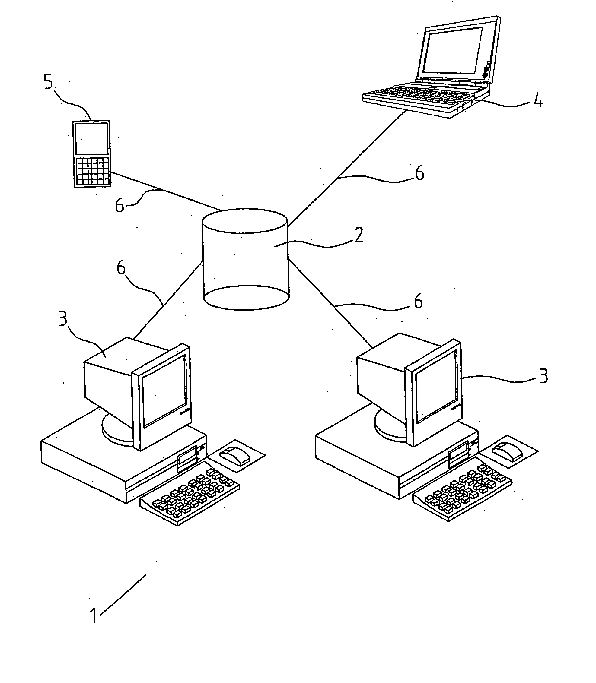
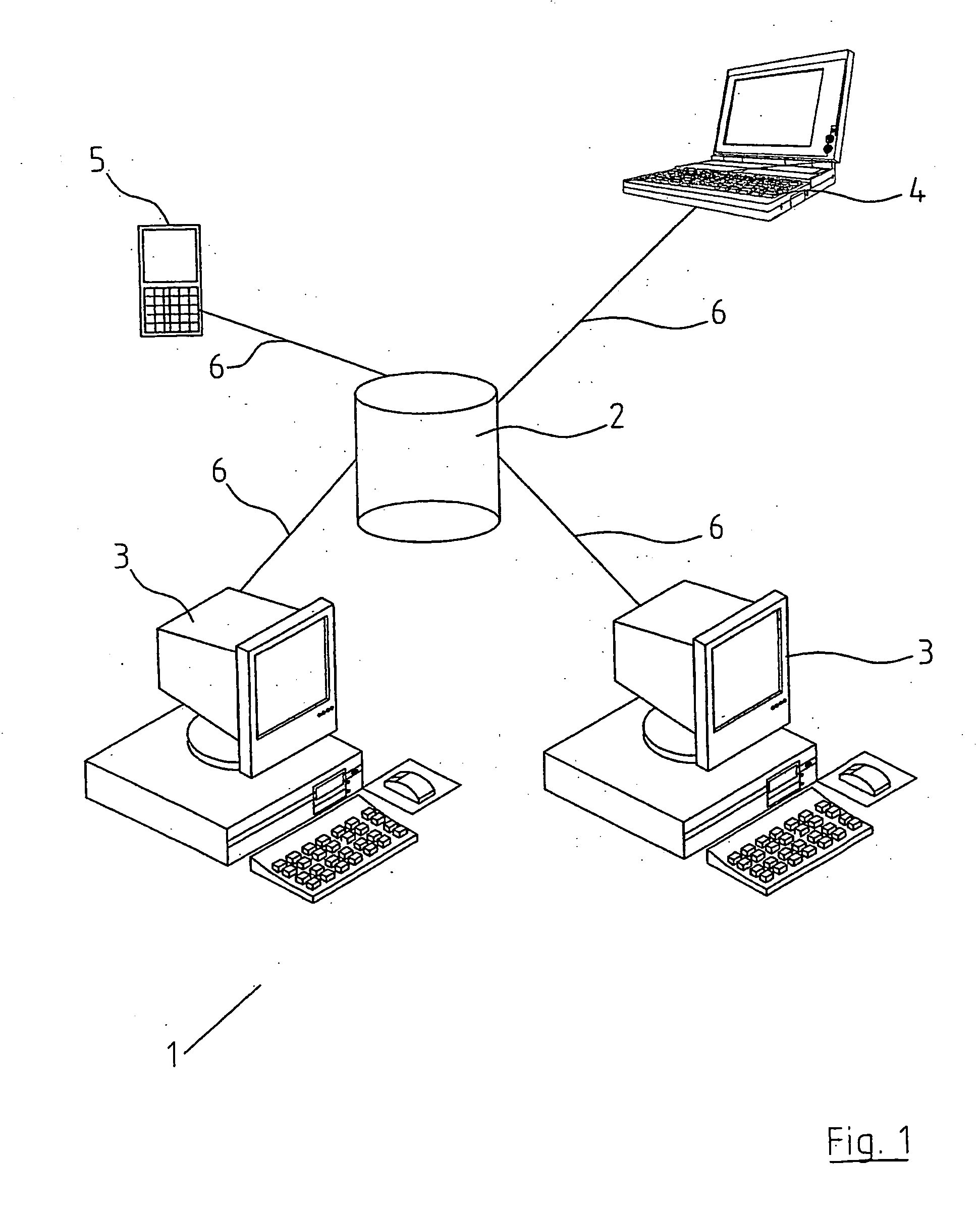
[0058]FIG. 1 is a diagrammatic view of a network incorporating the system;

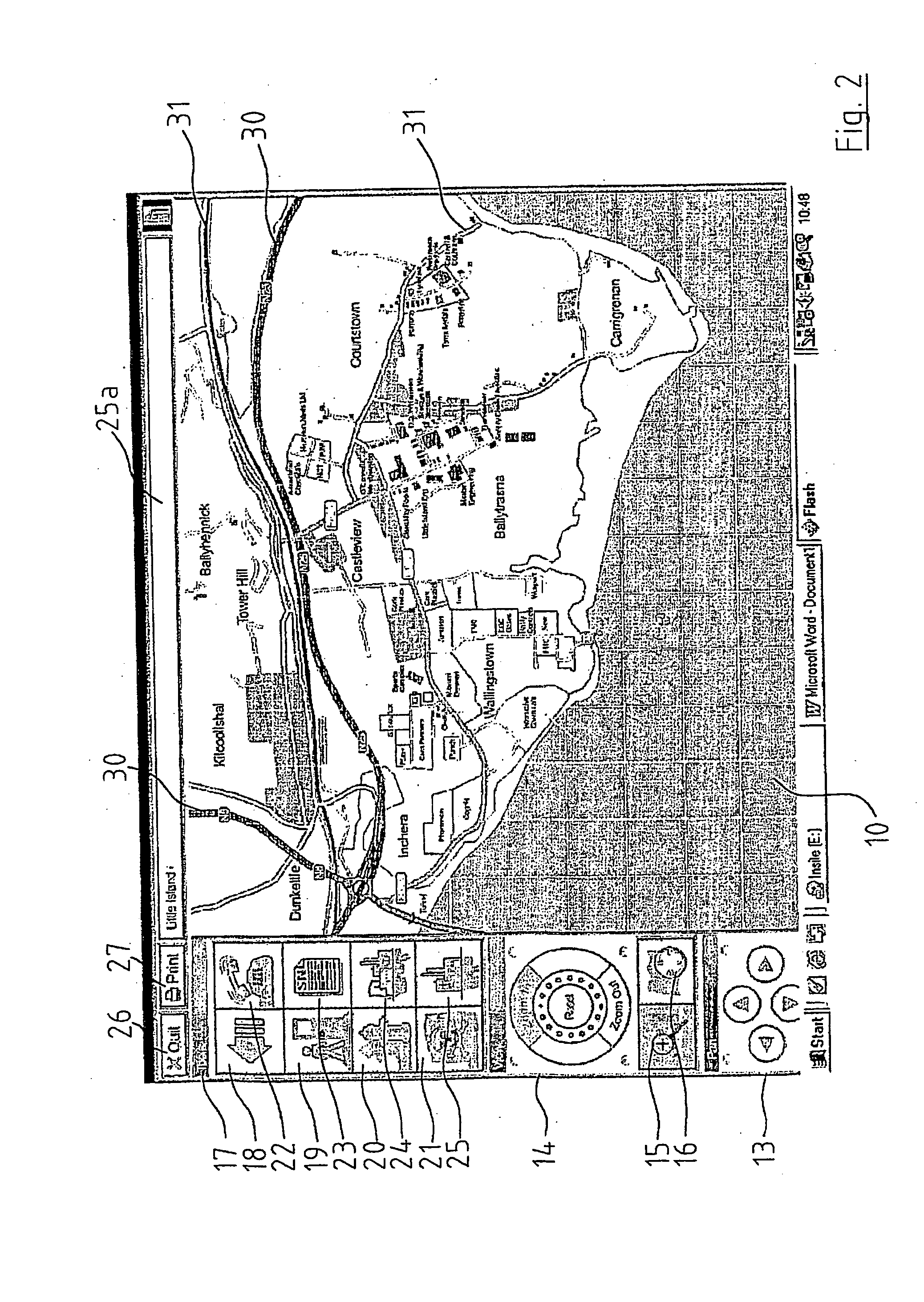
[0059]FIG. 2 is a screen shot showing a local area risk map;

[0060]FIG. 3 is the screen shot shown in FIG. 2 with display lists shown;

[0061]FIG. 4 is a screen shot of a site risk map;

[0062]FIG. 5 is a screen shot of a building risk map and surrounds within a 3D site risk map;

[0063]FIG. 6 is a screen shot of a building risk map with surrounding buildings removed from view;

[0064]FIG. 7 is a screen shot showing the ground floor of the building shown in FIG. 6;

[0065]FIG. 8 is a screen shot showing the first floor of the building shown in FIG. 6; and

[0066]FIG. 9 is a screen shot showing the second floor of the building shown in FIG. 6.

[0067] Referring now to the drawings and initially to FIG. 1 thereof there is s...


PUM


Abstract

A risk mapping system (1) for use in crises management comprises a database (2) having a plurality of risk maps and hazard data associated with each risk map stored thereon. The database is accessible by one or more of personal computers (3), laptops (4) and hand held devices (5) by way of communication channels (6). The risk maps stored on the database comprise three dimensional graphical representations of specific locations and for each specific location having a three dimensional graphical representation there are provided a plurality of three dimensional, graphical representations from different aspects of that location. The hazard data is represented by way of a hazard icon superimposed on the risk map.

Description

[0001] The present invention relates to a risk mapping system and in particular to a risk mapping system for use by the emergency services in crisis management. [0002] One of the major problems experienced by emergency services personnel, and in particular members of the fire services, is that there is often great difficulty in accessing emergency data such as blast radius, neighbouring sites and hazards, location of people and essential equipment such as fire hydrants, hose reels, valves and the like when arriving at the scene of an emergency. Valuable time may be lost in the search for such equipment which is unacceptable. [0003] Another problem experienced by fire service personnel is that often they are not-aware of the dangers awaiting them inside a building. For instance, whether or not there are certain chemicals or explosives inside the building that would affect the equipment used by the fire services as well as the strategy to be adopted for fighting the blaze. An unwary f...

Claims


Application Information

Patent Timeline
Patent Type & Authority Applications(United States)
IPC IPC(8): G06F19/00G06T17/05G06T17/40
CPCG06T17/05G06T19/00G06F17/30241Y10S707/99948Y10S707/99943Y10S707/99945Y10S707/99937G06T2200/24G06F16/29
Inventor SULLIVAN, ANDREWSULLIVAN, VICTORTHOMPSON, DIANAO'DONOVAN, FERGALDUANE, SEAN
Owner IND INTERFACES
Why Eureka
Try Eureka