Heddle with reduced play

a technology of reducing play and reducing load, which is applied in the field of heddle, can solve the problems of dynamic deformation that cannot be avoided entirely, high dynamic load on the heddle support rail and the heddle, etc., and achieves the effect of reducing mass, reducing the force that is required for acceleration and braking, and reducing siz

Inactive Publication Date: 2005-04-28
GROZ BECKERT KG
View PDF8 Cites 10 Cited by
  • Summary
  • Abstract
  • Description
  • Claims
  • Application Information

AI Technical Summary

Benefits of technology

[0010] The weaving heddle of the invention, in comparison to known weaving heddles, has an end eyelet of reduced size, whose inner free space has a height of at most 19.5 mm. This provision by itself already reduces the weight of the end eyelets compared to end eyelets that meet the ISO standard. The reduced mass reduces the forces that are required for accelerating and braking considerably. Moreover, the reduced height of the inner free space of the end eyelet makes it compulsory to use heddle support rails of reduced cross section and in particular reduced height. Although this lessens the rigidity of the heddle support rail, nevertheless the mass of the heddle support rails is also reduced considerably. At high accelerations, which are usual in modem power looms, the reduced mass reduces the forces of inertia more than would be necessary to compensate for the loss in rigidity. In conjunction with the reduction in the mass of the weaving heddles, the result is the capability of increasing the operating speed of a corresponding power loom.
[0011] The invention in particular takes into account the tendency to use more-rigid heddle shafts. If the height of the free space of the C-shaped end eyelet is defined at a value of at most 19.5 mm, and if the height of the heddle support rail is 18 mm, for instance, the result is a longitudinal play (axial play) of the heddles of at most 1.5 mm. Compared to conventional heddle support rail systems, the longitudinal play of the heddles is reduced by a factor of 2 to 3. In cooperation with the use of rigid heddle shafts, higher speeds can be attained. The reduced heddle play in particular when the more-rigid heddle shafts are used reduces annoying noise and wear to the heddle support rails and heddle end eyelets.
[0012] The reduced height of the free space of the end eyelet leads to a reduced length of the end eyelet. If the end eyelet spacing remains the same, the total external length of the heddle thus drops. The heddle shaft therefore requires less space for receiving the heddles, and as a result the shaft rods can attain a greater breadth, measured in the direction of motion of the heddle shaft, while preserving the same external dimensions of the heddle shaft. As a result, they become substantially more rigid, which can be utilized to increase the operating speed of the power loom. Thus decreasing the height of the free space of the C-shaped end eyelet is the precondition for extensive optimization of heddle shafts in terms of the operating speed, noise, and wear.
[0013] The heddle support rail preferably now has a breadth of only about 1.5 mm; at least in a preferred embodiment, it is provided on at least one side with a longitudinally continuous indentation, or a plurality of individual indentations in line with one another. This indentation serves on the one hand to make the heddle support rail lighter in weight and on the other to make it possible to secure the heddle support rail to a shaft profile or to a connecting means with the shaft profile in a simple, secure way by means of a plurality of rivets. In the aforementioned indentation or groove, a half-round head of the rivet can be accommodated without hindering the displaceability of the heddles. The groove or indentation is also advantageous, since in what at 1.5 mm is a very thin heddle support rail, adequate countersinking for the rivet head can no longer be achieved reliably enough. The requisite effort and expense for adhering to close tolerances in achieving the functional reliability would be too high and hence uneconomical.

Problems solved by technology

With increasing operating speed of the power looms, the shedding must be done faster and faster, which leads to high dynamic loads on the heddle support rails and the heddles.
However, these dynamic deformations can never be avoided entirely, because of the masses that must be accelerated and braked, which are brought to bear by the heddle shaft itself and by the heddle support rails, the heddles, and the warp yams that pass through the heddles.

Method used


Image

  • Heddle with reduced play
  • Heddle with reduced play
  • Heddle with reduced play

Examples


Embodiment Construction

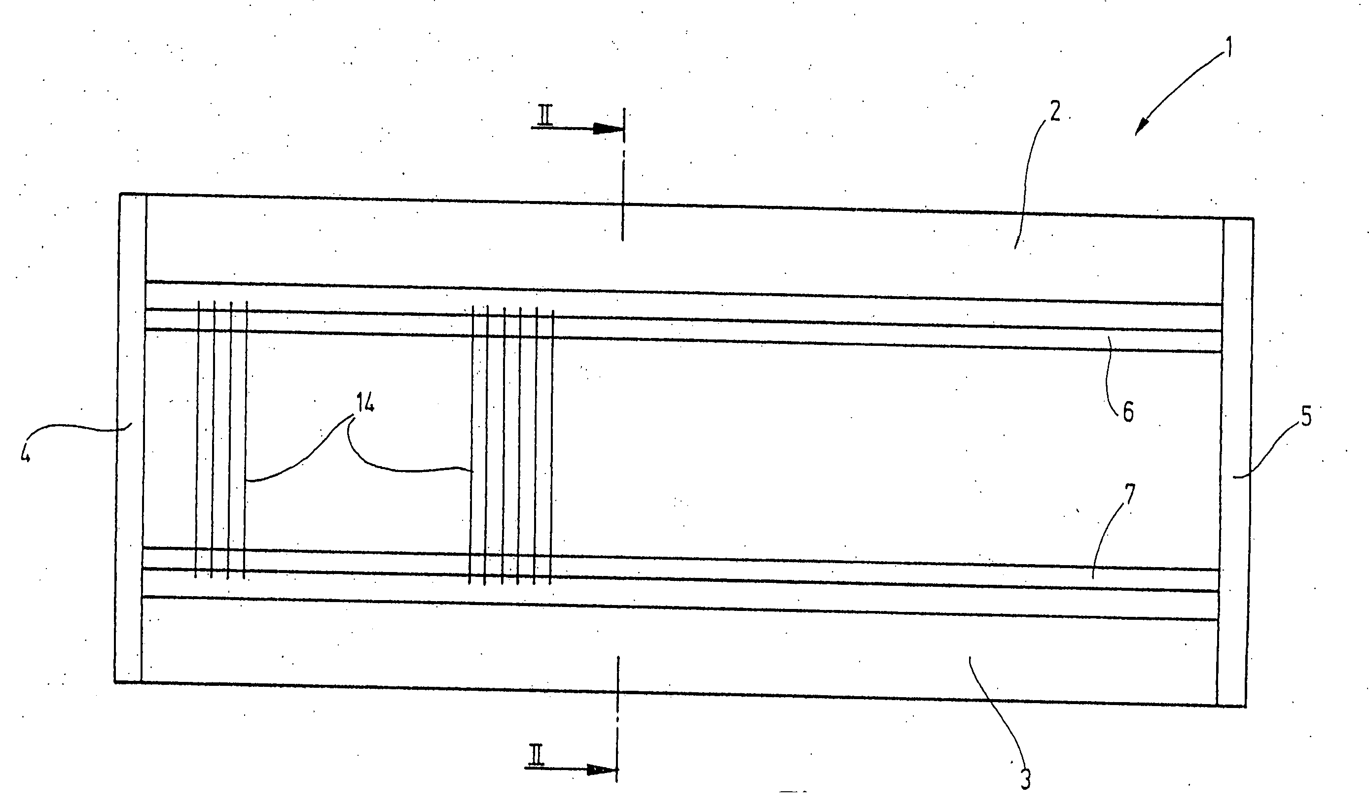
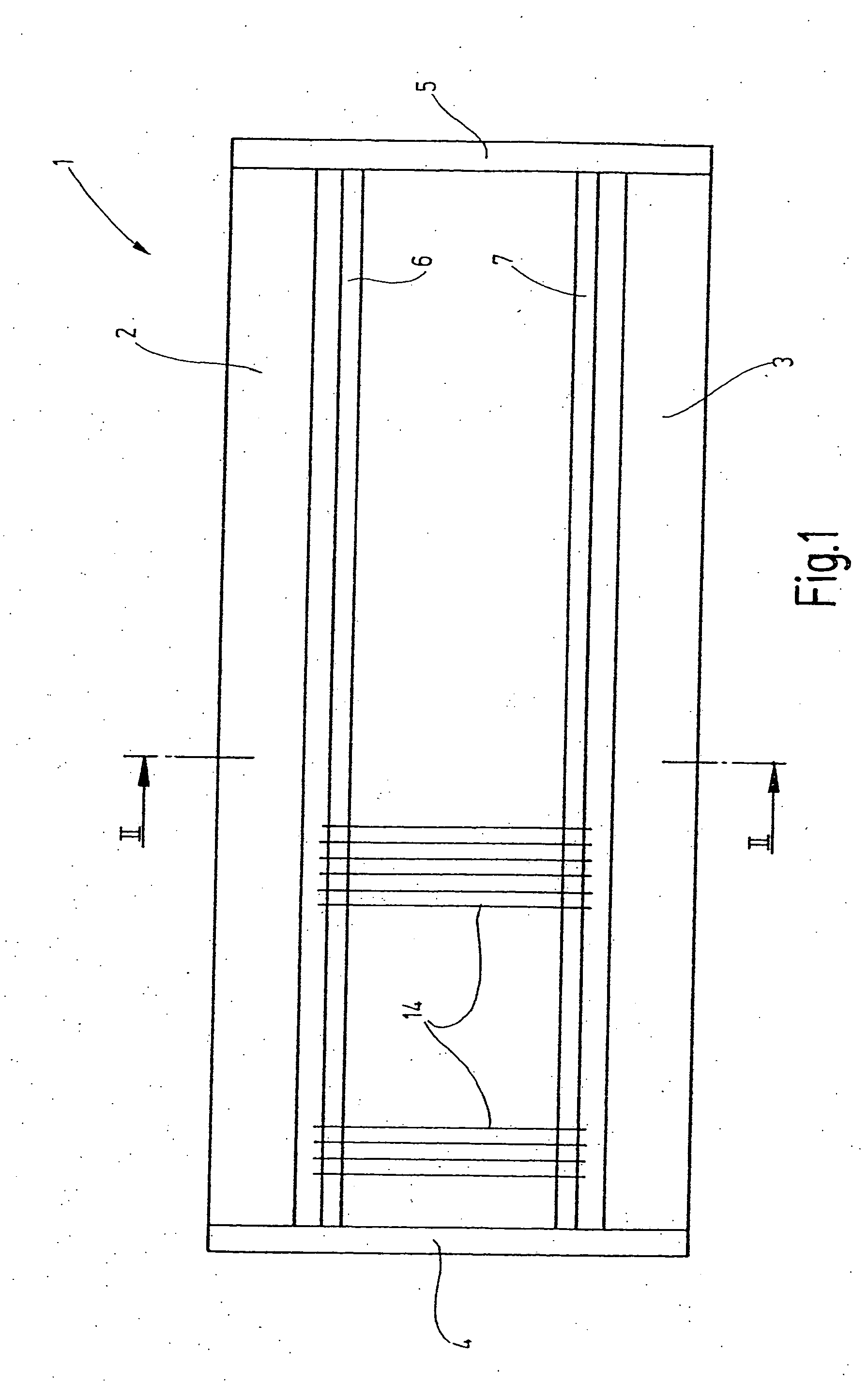
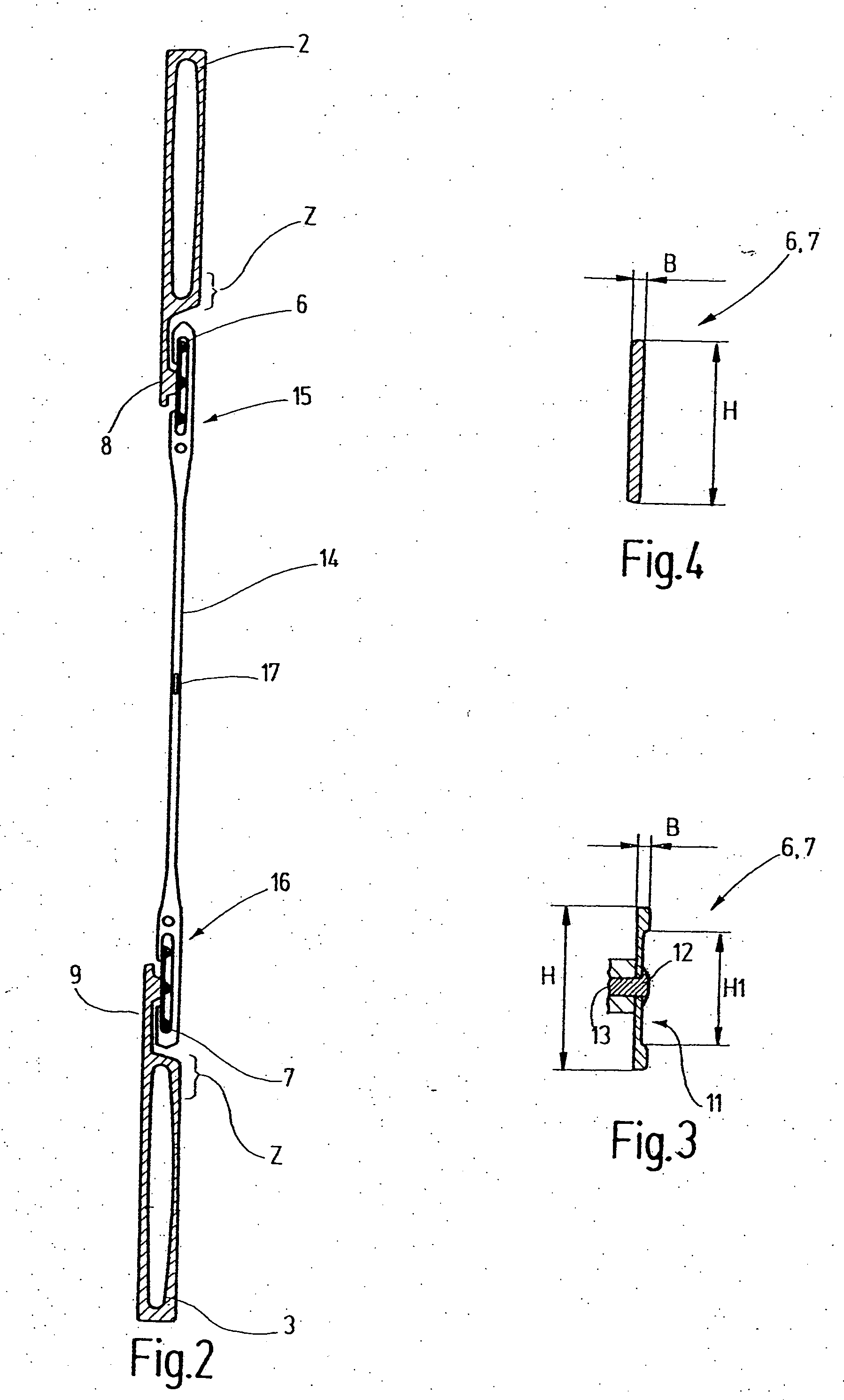
[0024] In FIG. 1, a heddle shaft 1 is shown, which has an upper shaft rod 2 and a lower, second shaft rod 3, disposed parallel to it at a distance. The ends of the shaft rods 2, 3 are joined together by side struts 4, 5, forming a firm rectangular frame. One heddle support rail 6, 7 each is retained on the upper and on the lower shaft rod 2, 3, as can also be seen from FIGS. 2 and 3. To that end, the shaft rods 2, 3 have extensions 8, 9, which support the heddle support rail 6, 7. As FIG. 3 shows, the heddle support rail is preferably embodied in the form of a flat steel profile, whose breadth B is preferably at most 1.5 mm and whose height H is preferably 18 mm. The cross section is approximately rectangular; the heddle support rail 6, 7 is provided with a rounding on its top side. It may be provided, as FIG. 3 shows, at selected points with an indentation 11, whose height H1 is at most 14 mm and whose length (perpendicular to the plane of the drawing) is for instance 11 mm. As a r...


PUM


Abstract

A heddle (14) of the invention is distinguished by end eyelets (15, 16) of reduced size, with which heddle support rails (6, 7) of reduced cross section are associated. The axial play of the heddles on the heddle support rails (6, 7) is limited to from 0.5 mm to 1.5 mm. The lateral play is in the range of 0.2 mm to 0.5 mm. This system formed of heddle support rails and heddles is especially suitable for particularly rigid heddle shafts for power looms with an extremely high operating speed.

Description

CROSS REFERENCE TO RELATED APPLICATION [0001] This application claims the priority of German Patent Application No. 103 42 577.2, filed on Sep. 15, 2003, the subject matter of which, in its entirety, is incorporated herein by reference. FIELD OF THE INVENTION [0002] The invention relates to a heddle and its support rail, as well as to the system formed of the support rail and heddles seated on it. BACKGROUND OF THE INVENTION [0003] Power looms, for forming sheds or shedding, have heddle shafts with heddles that are retained on support rails. In operation, the heddle shafts are moved back and forth for shedding. With increasing operating speed of the power looms, the shedding must be done faster and faster, which leads to high dynamic loads on the heddle support rails and the heddles. [0004] Shedding using heddle shafts on which heddles are retained is an old fundamental principle that has been employed for a long time. For instance, U.S. Pat. No. 2,047,511 discloses on such heddle s...

Claims


Application Information

Patent Timeline
Patent Type & Authority Applications(United States)
IPC IPC(8): D03C9/02D03C9/00D03C9/06D03C13/00
CPCD03C9/0633D03C9/02
Inventor METTLER, FRANZ
Owner GROZ BECKERT KG
Why Eureka
Try Eureka