Loudspeaker enclosure

a loudspeaker and enclosure technology, applied in the field of loudspeakers, can solve the problems of complex prior art transmission line enclosures, and undesirable non-linear standing wave effects, and achieve the effects of minimizing resonant standing wave or sound cancellation effects, reducing noise, and reducing nois

Inactive Publication Date: 2005-04-28
FLANDERS ANDREW E +2
View PDF15 Cites 36 Cited by
  • Summary
  • Abstract
  • Description
  • Claims
  • Application Information

AI Technical Summary

Benefits of technology

[0022] A loudspeaker enclosure is arranged to support at least one electromagnetic loudspeaker driver generating both front and back acoustic waves. The front of the speaker is substantially planar and the driver is mounted in an opening in the front of the enclosure to radiate forwardly. The driver 's back wave communicates through a passage adapted to function as an impedance-matched transmission line cavity having a length that is, preferably three times the driver cone's diameter, and having one or more ports terminating in openings defined in a plane that is, preferably, substantially perpendicular to the enclosure's planar front. The port or ports have a cross sectional area of 0.5 to about 2.0 times the operative area of the driver cone of the loudspeaker (preferably 0.707 to 1.414 times the operative area of the driver cone), thereby giving a highly efficient means of sound propagation.
[0023] The enclosure may also support optional high frequency “tweeter” speakers, which provide one or more planes of sound propagation depending on the usage environment. The architecture of the internal speaker box design provides various reflectors and deflectors to provide the most direct path of sou...

Problems solved by technology

Both forms of enclosure contribute to sound which may be characterized as less than desirable in bass reproduction, fidelity and liveliness.
Both the sealed box loudspeakers and the vented box loudspeakers essentially reflect the driver's back wave within the box, causing undesirable non-linear standing wave effects.
Prior art transmission line enclosures are complicated and have serpentine-like long acoustic paths ofte...

Method used


Image

  • Loudspeaker enclosure
  • Loudspeaker enclosure
  • Loudspeaker enclosure

Examples


Embodiment Construction

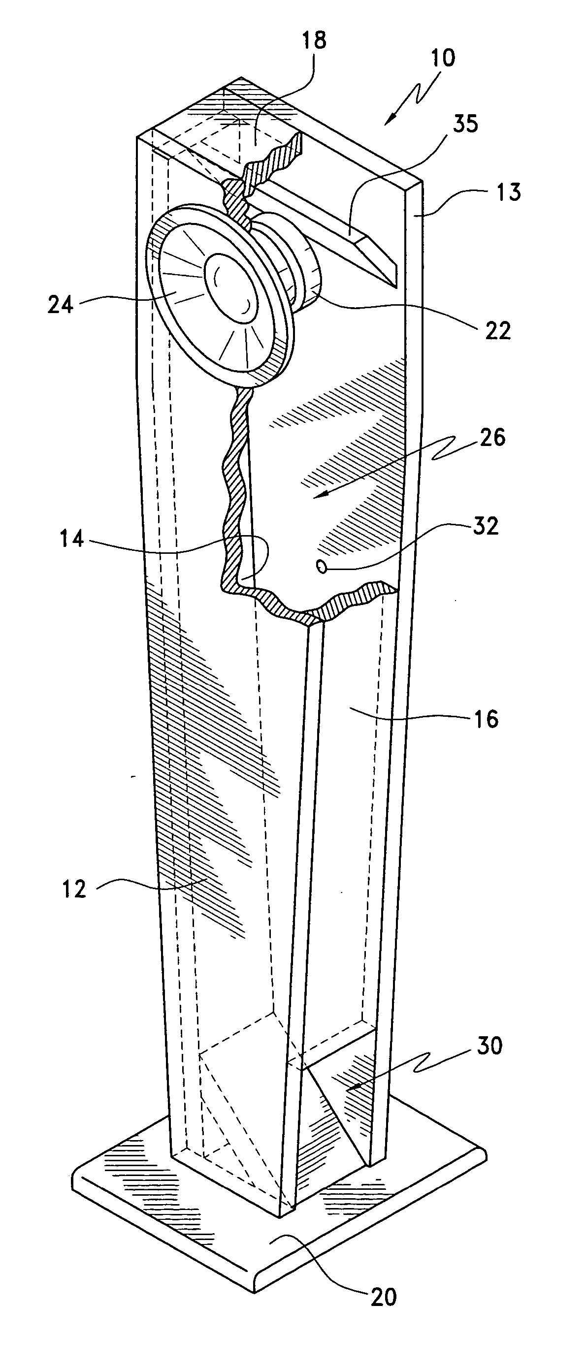
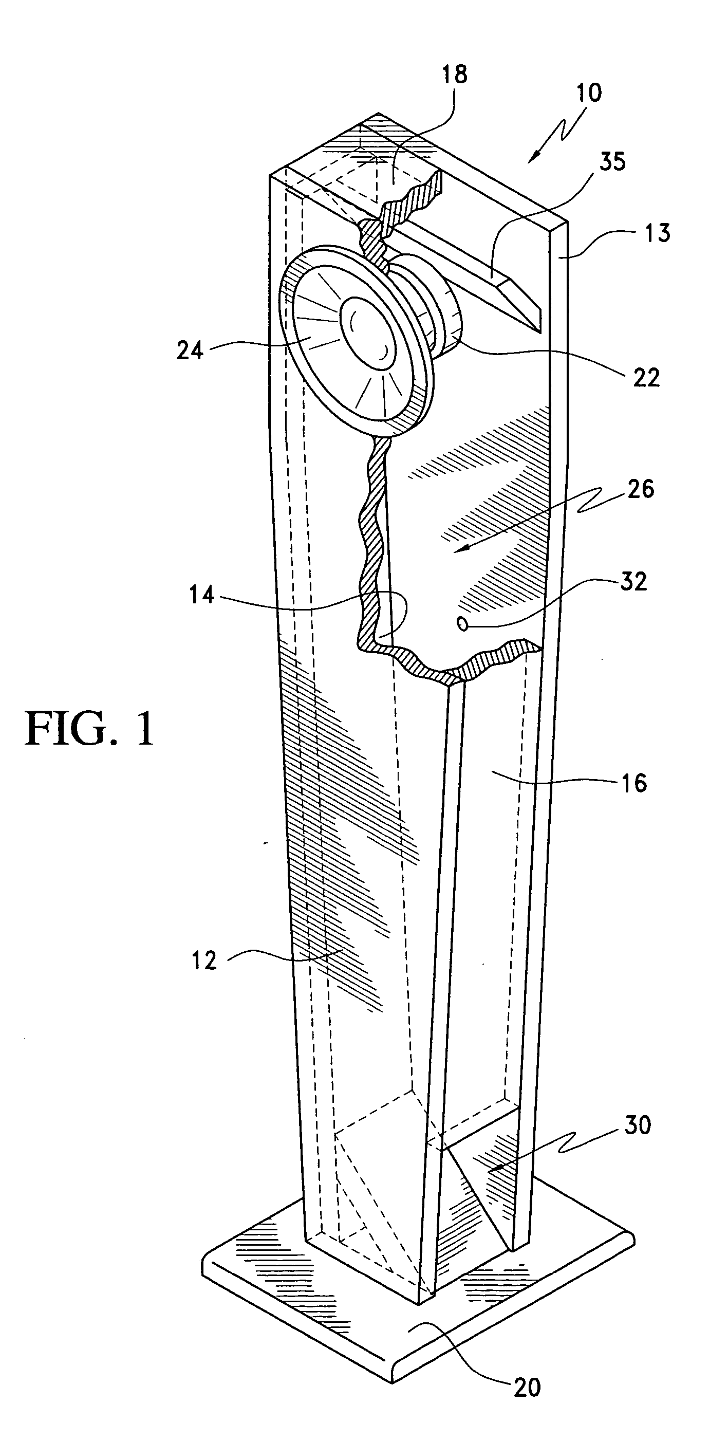
[0057] With reference to FIGS. 1, 2 and 3, a loudspeaker enclosure 10 includes a substantially planar front baffle 12 joined at opposing sides in intersections or joints to sealably engage opposing substantially planar first and second side walls, 14, 16. Front baffle 12 is terminated at its top edge with enclosure top end wall 18 and at its bottom edge with enclosure bottom wall or plinth 20, to sealably engage in intersections or joints. A substantially planar rear wall 13 is supported in a substantially parallel relationship with front baffle 12. Rear wall 13 is joined at opposing sides in intersections or joints to sealably engage first and second side walls, 14, 16. Rear wall 13 is terminated at its top edge with enclosure top end wall 18 and at its bottom edge with enclosure bottom wall or plinth 20, to sealably engage in intersections or joints, to define an enclosure interior volume 26 containing a column of air.

[0058] In the preferred embodiment, front baffle 12, first sid...


PUM


Abstract

A loudspeaker enclosure is arranged to support at least one electromagnetic loudspeaker driver generating both front and back acoustic waves. The front of the speaker is substantially planar and the driver is mounted in an opening in the front of the enclosure to radiate forwardly. The driver's back wave communicates through a passage adapted to function as an impedance-matched transmission line cavity having a length that is, preferably, three times the driver cone's diameter, and having one or more ports terminating in openings defined in a plane that is, preferably, substantially perpendicular to the enclosure's planar front. The port or ports have a cross sectional area of, preferably 0.707 to 1.414 times the operative area of the driver cone, thereby giving a highly efficient means of sound propagation.

Description

CROSS REFERENCE TO RELATED APPLICATIONS [0001] This application claims the benefit of priority under 35 U.S.C. 119(e) of U.S. Application No. 60 / 502,199, which was filed on Sep. 12, 2003, the entire disclosure of which is incorporated herein by reference.BACKGROUND OF THE INVENTION [0002] 1. Field of the Invention [0003] The present invention relates in general to loudspeakers for sound reproduction or sound reinforcement, and methods of building acoustically efficient enclosures for loudspeakers that permit high accuracy reproduction. [0004] 2. Description of the Background Art [0005] Loudspeaker enclosures of the prior art generally include a front opening adapted to receive a loudspeaker driver for directing the front acoustic wave of a loudspeaker forwardly into a room or other space. Prior art enclosures are often categorized in one of two large groups, namely sealed boxes or vented boxes. [0006] Sealed box or infinite baffle loudspeaker enclosures customarily include a selecte...

Claims


Application Information

Patent Timeline
IPC IPC(8): A47B81/06H04R1/26H04R1/28H05K5/00
CPCH04R1/2857H04R1/26
Inventor FLANDERS, ANDREW E.JUDAH, BRADLEY E.BARTHA, ANDREW
Owner FLANDERS ANDREW E
Why Eureka
Try Eureka