Spectral measurnig device

a spectral measurement and device technology, applied in the field of spectrometering equipment, can solve the problems of inability to achieve an accurate measurement or a desired measurement, limit the size of such a turret, and the dead time attributable, so as to reduce the extent of chamber deformation during the evacuation

Inactive Publication Date: 2005-04-28
TOCHIGI NIKON CORP +1
View PDF2 Cites 17 Cited by
  • Summary
  • Abstract
  • Description
  • Claims
  • Application Information

AI Technical Summary

Benefits of technology

[0024] By forming a peripheral wall portion of a chamber in a cylindrical shape, the extent of chamber deformation during the evacuation can be reduced.

Problems solved by technology

If there are molecules that absorb the light in the wavelength range needed for the measurement exist in the optical path in such an optical apparatus, it may not be possible to achieve an accurate measurement or a desired measurement.
However, since the holder which holds the measurement object is disposed together with the optical system within a single chamber, the vacuum state inside the chamber needs to be released and then the chamber needs to be reevacuated every time the measurement object is replaced, resulting in dead time attributable to the wait period necessitated during a replacement.
However, there is a limit to how big such a turret can be without the apparatus itself becoming bulky, and thus, there is a limit to the number of measurement objects that can be mounted at the turret.
For this reason, dead time still occurs when a large number of measurement objects need to be measured.

Method used


Image

  • Spectral measurnig device
  • Spectral measurnig device
  • Spectral measurnig device

Examples


first embodiment

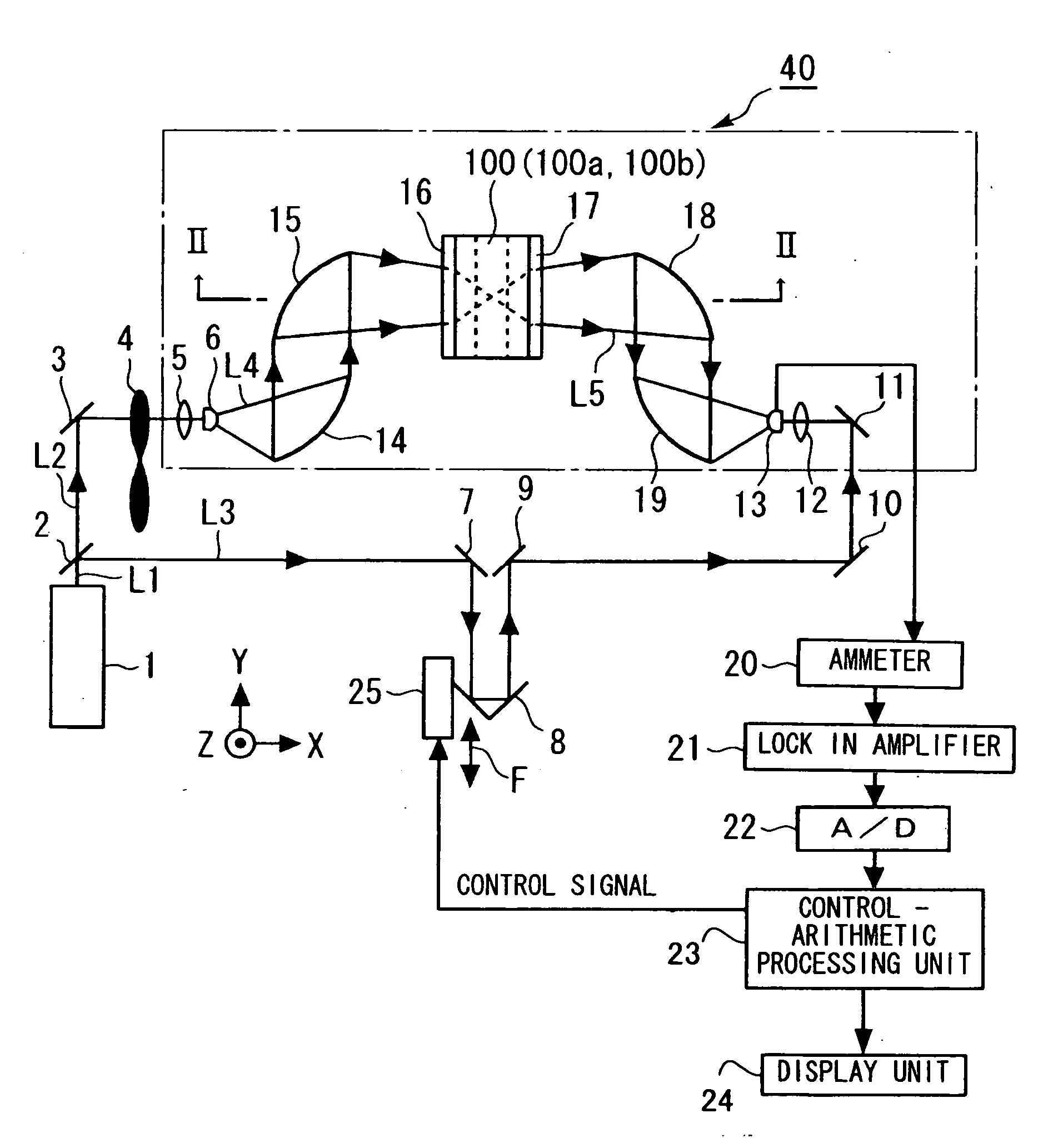
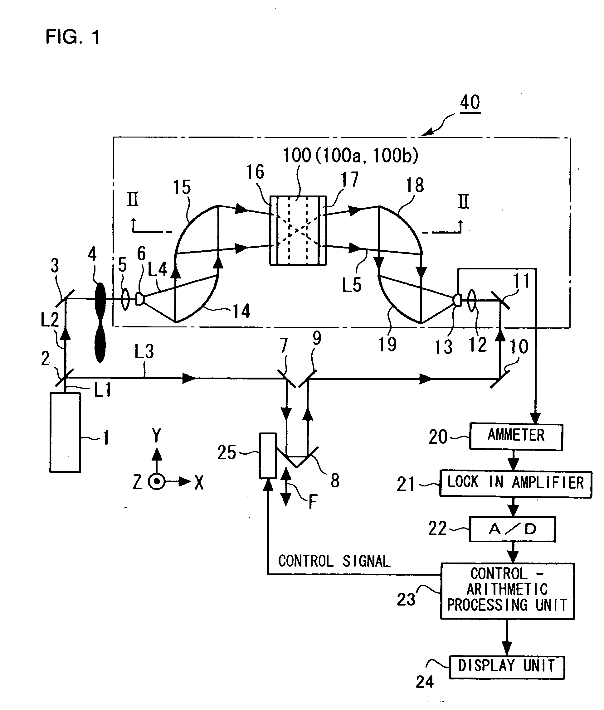
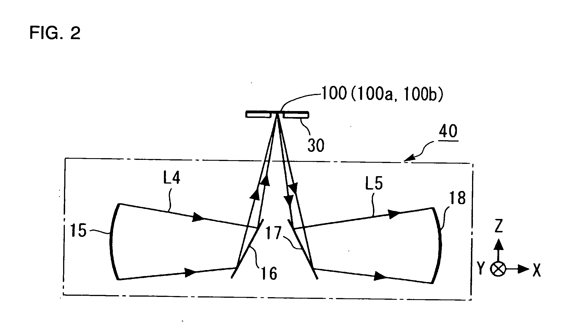
[0040]FIG. 1 is a schematic diagram showing the structure of the optical apparatus achieved in the first embodiment of the present invention. FIG. 2 is a schematic sectional view taken along line II-II in FIG. 1. In order to ensure that the invention is understood with ease, an X axis, a Y axis and a Z axis intersecting one another at a right angle are defined as shown in FIGS. 1 and 2. The XY plane is a horizontal plane, the Z axis extends along the vertical direction, the +Z direction extends upward along the vertical direction and the −Z direction extends downward along the vertical direction. FIG. 3 is a schematic perspective of the structure adopted in the optical apparatus in the embodiment. FIG. 4 is a schematic sectional view taken along line IV-IV in FIG. 3.

[0041] The optical apparatus achieved in the embodiment is utilized to measure the complex dielectric constant or the like of a specimen 100, i.e., the measurement object, by using terahertz light.

[0042] In the optical...

second embodiment

[0086]FIG. 5 is a schematic perspective showing the structure adopted in the optical apparatus in the second embodiment of the present invention. FIG. 6 is a schematic sectional view taken along line VI-VI in FIG. 5.

[0087] The main differences that distinguish the optical apparatus achieved in this embodiment from the optical apparatus in the first embodiment are described in (i) to (iii) below. [0088] (i) Its upper lid 52 is constituted with two separate parts, i.e., a disk 152a at the center and an annular ring 152b disposed further out relative to the disk. The inner circumferential side of the annular ring 152b is fixed to the outer circumferential side of the disk 152a with bolts 153. A packing 154 is disposed between the annular ring 152b and the disk 152a so as to fix the annular ring 152b and the disk 152a to each other with an airtight seal. [0089] (ii) The optical system mounting base 53 is set on an annular support plate 155 disposed near the bottom of the container main...

third embodiment

[0093]FIG. 7 is a schematic perspective showing the structure adopted in the optical apparatus in the third embodiment of the present invention. FIG. 8 is a schematic sectional view taken along line VII-VII in FIG. 7.

[0094] The main differences that distinguish the optical apparatus achieved in this embodiment from the optical apparatus in the first embodiment are described in (i) and (ii) below.

[0095] (i) The length of the connecting rods 54a to 54c is set greater than the depth of the container main body 51 and the mounting base 53 is mounted on the bottom of the container main body 51 via bolts 59. Thus, the structural body constituted with the specimen holder 30, the optical system 40, the optical system mounting base 53 and the connecting rods 54a to 54c is supported from below at the bottom of the container main body 51 instead of being supported in a suspended state.

[0096] (ii) A cylindrical member 251 is provided over the upper lid 52, thereby forming a chamber 250 which ...


PUM

PropertyMeasurementUnit
dielectric constantaaaaaaaaaa
frequencyaaaaaaaaaa
optical path lengthaaaaaaaaaa

Abstract

A holder (30) that holds a specimen (100) is disposed outside a vacuum chamber (50) with a light transmission window (52a). A light detection unit and a light radiation unit having a terahertz light generator (6) are fixed on a base (53) disposed inside the vacuum chamber. The light radiation unit irradiates terahertz pulse light onto the specimen (100) placed outside the vacuum chamber via the light transmission window (52a) and the resulting specimen light from the specimen (100) is received at the light detection unit via the light transmission window (52a). The base (53) in the vacuum chamber and the holder (30) disposed outside the vacuum chamber are connected via a connecting member (54a) passing displaceably through a barrier wall of a vacuum chamber (50) with airtight sealing so as to fix the relative position of the holder to the base.

Description

[0001] The disclosure of the following priority application is herein incorporated by reference: [0002] Japanese Patent Application No. 2001-399510 filed Dec. 28, 2001 TECHNICAL FIELD [0003] The present invention relates to a spectrometering apparatus that radiates light with a predetermined wavelength onto a specimen and measures the spectral characteristics of the specimen by detecting light from the specimen. BACKGROUND ART [0004] Optical apparatuses utilized as various types of measuring apparatuses each comprise a holder that holds the measurement object and an optical system that radiates a predetermined type of light onto the measurement object and effects an optical action on light obtained from the measurement object. [0005] Examples of such optical apparatuses that use terahertz light include spectroscopes, dielectric constant measuring apparatuses, inspection apparatuses, imaging apparatuses that generate an image indicating the dielectric constant distribution in the mea...

Claims


Application Information

Patent Timeline
Patent Type & Authority Applications(United States)
IPC IPC(8): G01N21/03G01N21/15
CPCG01N21/03G01N2021/151G01N21/3581
Inventor USAMI, MAMORUIWAMOTO, TOSHIYUKI
Owner TOCHIGI NIKON CORP
Why Eureka
Try Eureka