Eureka AIR delivers breakthrough ideas for toughest innovation challenges, trusted by R&D personnel around the world.

Amplifier pre-distortion processing based on composite look-up tables

Active Publication Date: 2005-04-28
COMMSCOPE TECH LLC
View PDF15 Cites 16 Cited by
  • Summary
  • Abstract
  • Description
  • Claims
  • Application Information

AI Technical Summary

Problems solved by technology

Amplifiers, such as high-power amplifiers used in the base stations of wireless communication systems, typically exhibit non-linearity over their operating ranges.
This non-linearity can result in noise that can corrupt or otherwise interfere with the communications.
Delaying RF signals can be expensive (e.g., about $1 for each nanosecond of delay).
Moreover, the larger the delay line, the greater the attenuation of the RF signal.
As such, gain is typically added to the amplifier to account for this attenuation, resulting in further cost and increased distortion.

Method used


Image

  • Amplifier pre-distortion processing based on composite look-up tables
  • Amplifier pre-distortion processing based on composite look-up tables
  • Amplifier pre-distortion processing based on composite look-up tables

Examples


Embodiment Construction

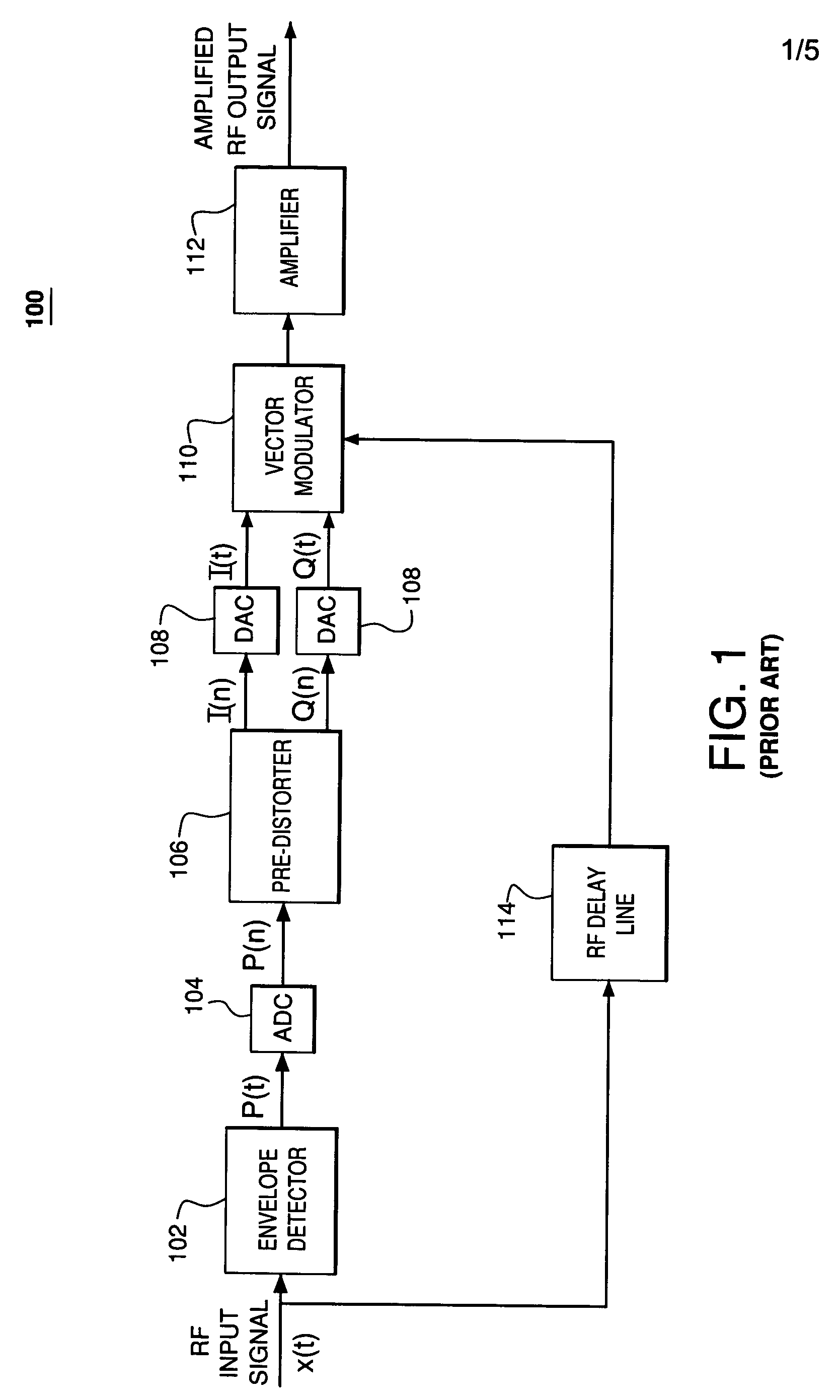
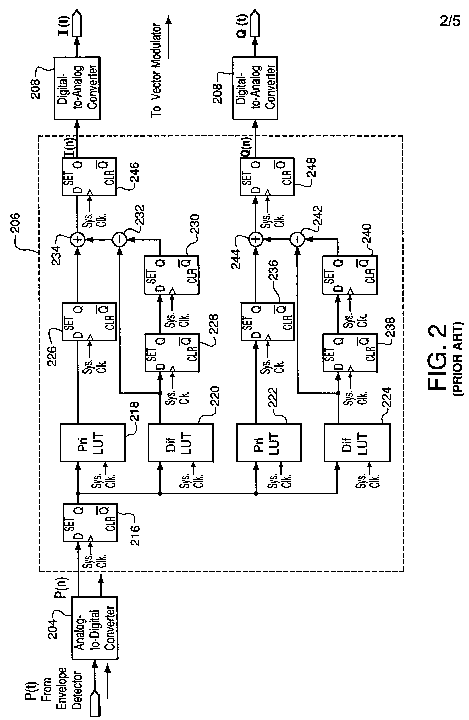
[0012]FIG. 2 shows a block diagram of prior art pre-distorter 206, which can be used to implement the pre-distorter of FIG. 1. In particular, FIG. 2 shows ADC 204 (similar to ADC 104 of FIG. 1) receiving an analog voltage signal p(t) generated by an envelope detector (similar to envelope detector 102 of FIG. 1) and generating a digital signal p(n) corresponding to that received voltage and representative of the instantaneous RF envelope power level. The digital power signal p(n) is applied to pre-distorter 206, which generates two digital pre-distortion components I(n) and Q(n), each of which is applied to a DAC 208 (similar to DACs 108 of FIG. 1) to generate analog pre-distortion signals I(t) and Q(t) that are applied to a vector modulator (similar to vector modulator 110 of FIG. 1) to generate a pre-distorted signal for amplification by an amplifier (similar to amplifier 112 of FIG. 1).

[0013] Pre-distorter 206 of FIG. 2 may be implemented in a field-programmable gate array (FPGA)...


PUM


Abstract

Current and previous input signal power measures are used to generate a combined index value that is applied to one or more composite look-up tables (e.g., an I LUT and a Q LUT) to retrieve one or more pre-distortion parameters (e.g., I and Q). In one embodiment, a combined index value is generated by concatenating current and previous power measures, where each composite LUT maps all possible combinations of the current and previous power measures to the corresponding pre-distortion parameters values. By using a composite LUT for each of I and Q, the overall signal processing time of the pre-distortion processing can be greatly reduced relative to the prior art, resulting in a significantly smaller RF delay line used to delay the input signal and thereby providing a less costly and more efficient amplifier system.

Description

FIELD OF THE INVENTION [0001] The present invention relates to signal processing, and, in particular, to techniques for linearizing amplifiers based on pre-compensation. BACKGROUND OF THE INVENTION [0002] Amplifiers, such as high-power amplifiers used in the base stations of wireless communication systems, typically exhibit non-linearity over their operating ranges. This non-linearity can result in noise that can corrupt or otherwise interfere with the communications. To address this problem, additional circuitry may be added to an amplifier in an attempt to linearize the effective amplifier response. Conventional techniques for linearizing amplifiers typically involve pre-compensation and / or feed-forward compensation. [0003] In amplifier linearization based on pre-compensation, the input signal that is to be amplified is pre-distorted prior to being applied to the amplifier in order to adjust the input signal based on known non-linearities in the amplifier transfer function. In fee...

Claims


Application Information

Patent Timeline
IPC IPC(8): H03F1/32
CPCH03F2201/3233H03F1/3294H03F1/32
Inventor JOHNSON, ROBERT E.YANG, RUIKANG
Owner COMMSCOPE TECH LLC
Why Eureka
Eureka Blog
Learn More