Clock signal generation apparatus, apparatus for generating a clock signal using an information recording medium, integrated circuit, clock signal generation method, and method for generating a clock signal using an information recording medium

a clock signal and information recording technology, applied in the field of clock signal generation apparatus, can solve the problems of affecting the quality of the clock signal, the inability to reproduce the recorded data after recording, and the change in the amplitude or duty ratio of the wobble signal, so as to achieve stable clock signal and precise phase comparison. , the effect of stable clock signal

Inactive Publication Date: 2005-04-28
PANASONIC CORP
View PDF6 Cites 9 Cited by
  • Summary
  • Abstract
  • Description
  • Claims
  • Application Information

AI Technical Summary

Benefits of technology

[0032] According to the present invention, an amplitude value of a wobble signal is integrated to obtain a first integrated value. Based on the first integrated value, a phase difference value is obtained. Based on the phase difference value, a control signal is generated. A frequency of the clock signal is adjusted based on the control signal. As a result, even when the quality of a wobble signal is deteriorated (e.g., distorted, etc.) due to noise or the like, highly precise phase comparison can be performed, thereby generating a stable clock signal.
[0033] According to one embodiment of the present invention, an absolute value of the amplitude of the wobble signal is integrated to obtain a second integrated value. Division is performed between the first integrated value and the second integrated value to obtain a phase difference value. By the division, a normalized phase difference value can be obtained with respect to the amplitude or cycle of the wobble signal. Therefore, the phase difference value can be obtained with a constant gain for a difference in phase angle between the wobble signal and the clock signal without being influenced by a variation in the amplitude of the wobble signal due to crosstalk or the like, resulting in a stable clock signal. In addition, even when a wobble cycle varies from format to format, a phase difference value can be obtained with a constant gain for a difference in phase angle. Therefore, a loop filter means having a simple structure can be employed.
[0034] According to another embodiment of the present invention, a dropout portion or a modulated portion indicating an address of a wobble signal is detected using the first integrated value and the second integrated value, thereby making it possible to generate a stable clock signal without being influenced by the dropout portion or the modulated portion.

Problems solved by technology

Therefore, as shown in FIG. 14, leakage (crosstalk) of reflected light from an adjacent track causes a change in the amplitude or duty ratio of a wobble signal, and noise causes jitter.
In the worst case, these influences cause the oscillation frequency of a clock signal to be unstable during data recording, so that recorded data cannot be reproduced after recording.
In this case, it takes a long time until data recording can be started, so that a high level of access performance cannot be assured.
Therefore, a recording apparatus capable of handling a plurality of formats needs to have a loop filter specialized for each -format, leading to a complex circuit structure.

Method used


Image

  • Clock signal generation apparatus, apparatus for generating a clock signal using an information recording medium, integrated circuit, clock signal generation method, and method for generating a clock signal using an information recording medium
  • Clock signal generation apparatus, apparatus for generating a clock signal using an information recording medium, integrated circuit, clock signal generation method, and method for generating a clock signal using an information recording medium
  • Clock signal generation apparatus, apparatus for generating a clock signal using an information recording medium, integrated circuit, clock signal generation method, and method for generating a clock signal using an information recording medium

Examples


embodiment 1

[0054] (Embodiment 1)

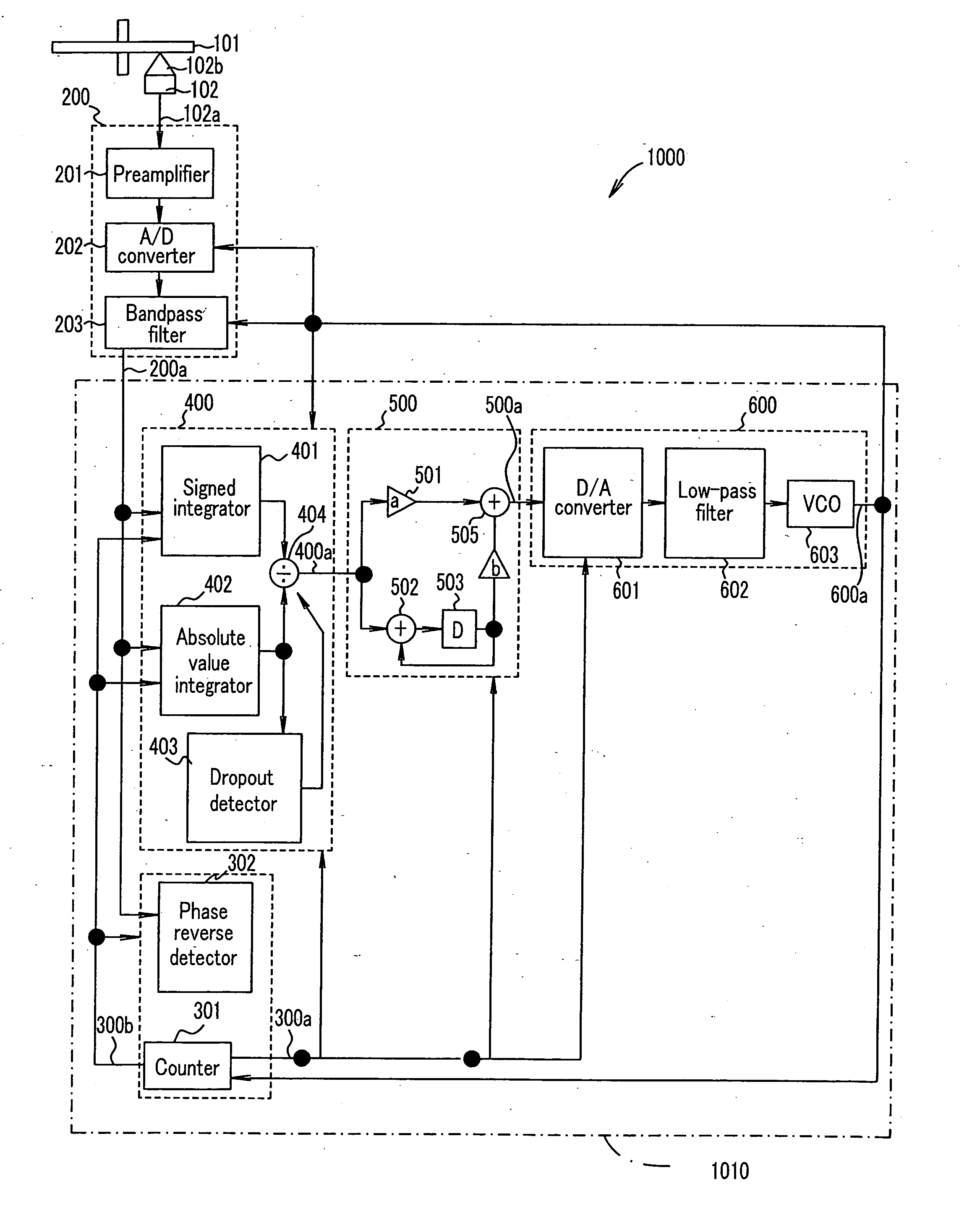
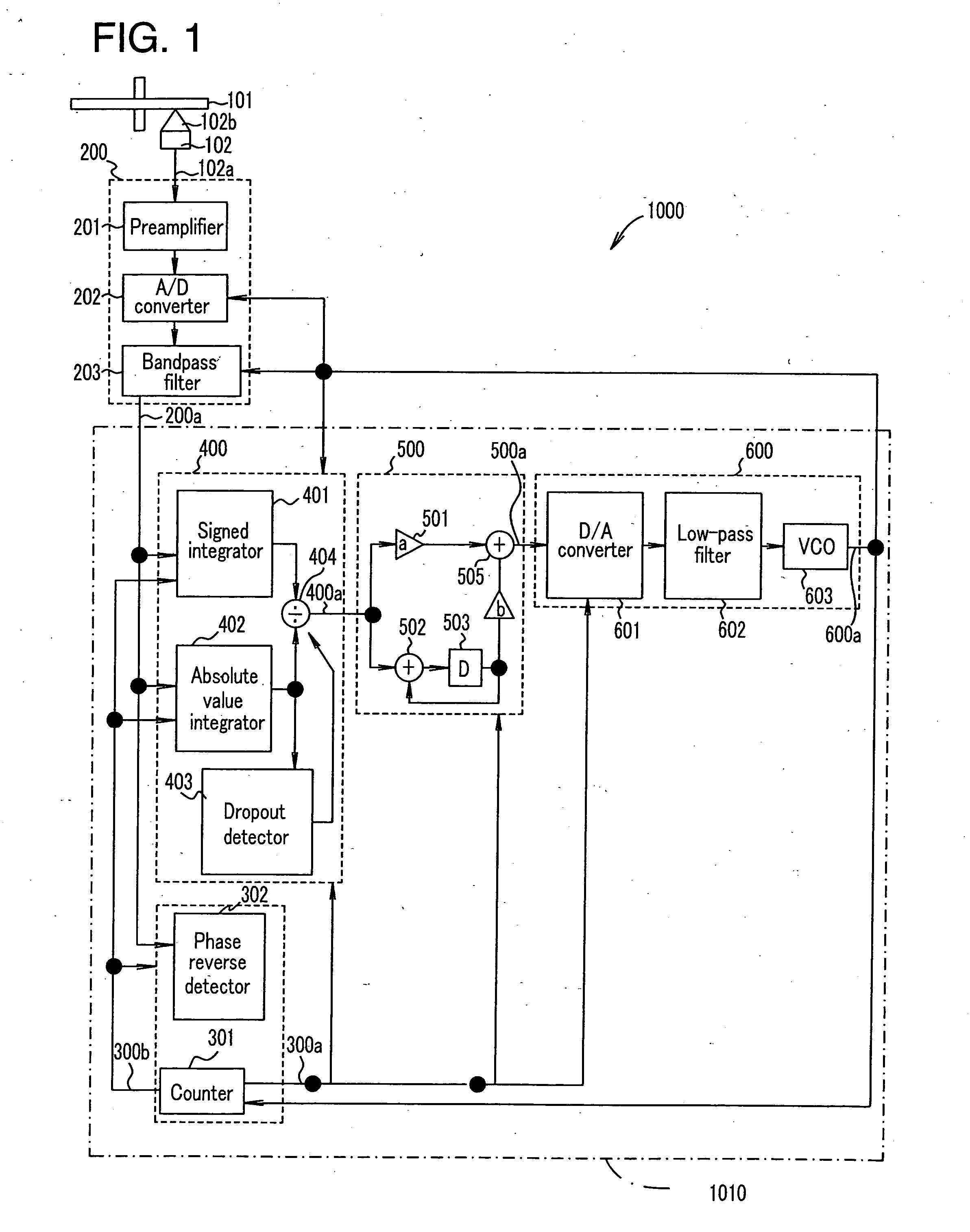
[0055]FIG. 1 is a block diagram showing a recording / reproduction apparatus 1000 according to Embodiment 1 of the present invention.

[0056] The recording / reproduction apparatus 1000 generates a clock signal using an information recording medium 101. The information recording medium 101 is a recordable medium which has at least one track in a wobbling shape, including, for example, an optical disc.

[0057] The recording / reproduction apparatus 1000 comprises an optical head section 102, a wobble detection circuit 200, and a clock signal generation apparatus 1010.

[0058] The optical head section 102 irradiates the information recording medium 101 with laser light 102b, detects an amount of reflected light from the information recording medium 101, and based on the amount of the reflected light, outputs a reproduction signal 102a.

[0059] The wobble detection circuit 200 functions as a wobble signal generation section, which generates a wobble signal based on the wobbl...

embodiment 2

[0087] (Embodiment 2)

[0088]FIG. 6 is a block diagram showing a recording / reproduction apparatus 1100 according to Embodiment 2 of the present invention. The recording / reproduction apparatus 1100 comprises a clock signal generation apparatus 1110. In FIG. 6, the same parts as those shown in FIG. 1 are indicated by the same -reference numerals and will not be explained further.

[0089] In Embodiment 2, the frequency or phase of a wobble of a track on an information recording medium 101 is modulated to represent an address.

[0090] Modulation of the frequency and phase of the wobble of a track will be described with reference to FIGS. 7A and 7B. FIGS. 7A and 7B show a waveform of a modulated wobble signal. In order to record data at a predetermined position, a recording side of the information recording medium 101 is provided with addresses along a track groove. The addresses are recorded by, for example, modulating the frequency or phase of the wobble of the track. Figure 7A shows a wav...

embodiment 3

[0102] (Embodiment 3)

[0103]FIG. 9A is a block diagram showing a recording / reproduction apparatus 1200 according to Embodiment 3 of the present invention. The recording / reproduction apparatus 1200 comprises a clock signal generation apparatus 1210. In FIG. 9A, the same parts as those shown in FIG. 1 are indicated by the same reference numerals and will not be explained further.

[0104] In Embodiment 3, as shown in FIG. 9B, an information recording medium 101 has track grooves 1121 and land prepits (LPP) 1123. The land prepits 1123 are previously formed between adjacent track grooves 1121 (i.e., a land 1122). The land prepit 1123 has a predetermined phase relationship with the wobble of the track groove 1121. The land prepit 1123 indicates an address.

[0105] A land prepit (LPP) will be described below. FIG. 10 shows a reproduction signal 102a including an LPP signal indicating an LPP. The LPP signal is included in a wobble component contained in the reproduction signal 102a. By compari...


PUM

PropertyMeasurementUnit
frequencyaaaaaaaaaa
phase comparisonaaaaaaaaaa
phase differenceaaaaaaaaaa

Abstract

A clock signal generation apparatus is provided for generating a clock signal synchronized with a wobble signal, which comprises an oscillation section for generating the clock signal, a counter section for generating a predetermined count value, a phase comparison section for integrating an amplitude value of the wobble signal over a predetermined interval specified based on the predetermined count value to obtain a first integrated value, and obtaining a phase difference value indicating a phase difference between the wobble signal and the clock signal based on the first integrated value, and a control signal generation section for generating a control signal based on the phase difference value, the control signal being used for controlling a frequency of the clock signal. The oscillation section adjusts the frequency of the clock signal based on the control signal.

Description

[0001] This non-provisional application claims priority under 35 U.S.C. §119(a) on Patent Application No. 2003-364248 filed in Japan on Oct. 24, 2003, the entire contents of which are hereby incorporated by reference. BACKGROUND OF THE INVENTION [0002] 1. Field of the Invention [0003] The present invention relates to an apparatus, an integrated circuit, and a method for generating a clock signal. [0004] 2. Description of the Related Art [0005] Conventionally, recordable optical disc media are provided with track grooves previously formed. Information is recorded along the track grooves. Specifically, information is recorded in the track groove or a region (land) interposed between the track grooves. The track groove meanders in a sine wave pattern. Information is recorded in synchronization with a clock signal which is generated based on cycles of the wobble. The clock signal is in synchronization with the wobble cycle. Such a clock signal is generally produced using a phase locked ...

Claims


Application Information

Patent Timeline
Patent Type & Authority Applications(United States)
IPC IPC(8): G11B20/14G11B27/24H03L7/091
CPCG11B20/1403G11B27/24G11B2220/216H03L7/091G11B2220/2562G11B2220/2575G11B2220/218
Inventor NAKATA, KOHEIUSUI, MAKOTOGUSHIMA, TOYOJINAKAJIMA, TAKESHI
Owner PANASONIC CORP
Why Eureka
Try Eureka