Fixed quantity supply equipment for inflators
- Summary
- Abstract
- Description
- Claims
- Application Information
AI Technical Summary
Benefits of technology
Problems solved by technology
Method used
Image
Examples
Embodiment Construction
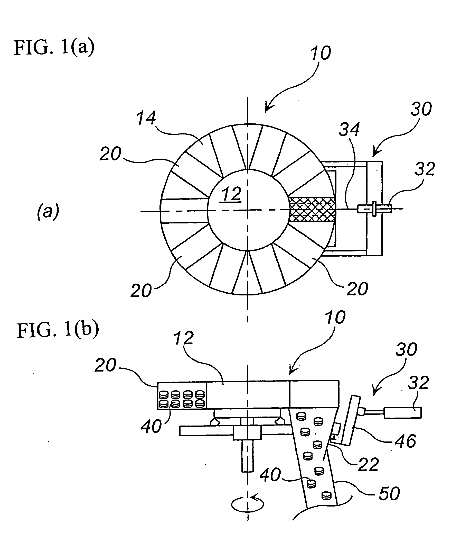
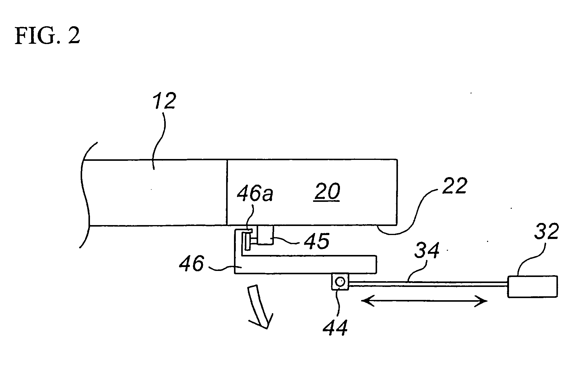
[0028] Hereinafter, an embodiment of the present invention will be explained with reference to the drawings. FIG. 1(a) is a plan view of a fixed quantity supply equipment for inflators, FIG. 1(b) is a front view of the apparatus in FIG. 1(a) and FIG. 2 is a partially enlarged view of the apparatus in FIG. 1.
[0029] A fixed quantity supply equipment for inflators 10 has a rotatable supporting shaft 12 connected to an unillustrated driving apparatus, an annular main body portion 14 integrally mounted at a periphery of the supporting shaft 12, inflator accommodating chambers 20 obtained by partitioning the annular main body portion 14 into plural chambers, and an opening / closing means 30. The annular main body portion 14 rotates on an annular guide rail (not shown) partially cut off.
[0030] The inflator accommodating chamber 20 has a cubic shape, and its volume is determined in relation to a size of an inflator 40 and the total number of inflators 40 to be accommodated. In FIG. 1(a), t...
PUM
 Abstract
Description
Claims
Application Information
 - R&D
- Intellectual Property
- Life Sciences
- Materials
- Tech Scout
- Unparalleled Data Quality
- Higher Quality Content
- 60% Fewer Hallucinations
Browse by: Latest US Patents, China's latest patents, Technical Efficacy Thesaurus, Application Domain, Technology Topic, Popular Technical Reports.
© 2025 PatSnap. All rights reserved.Legal|Privacy policy|Modern Slavery Act Transparency Statement|Sitemap|About US| Contact US: help@patsnap.com


