Cryogenic fuel tank insulation assembly

a fuel tank and assembly technology, applied in the direction of cosmonautic safety/emergency devices, vessel geometry/arrangement/size, non-pressured vessels, etc., can solve the problems of increasing the size of the vehicle, requiring considerable portions of the vehicle, and the strength and reusability requirements associated with multi-mission flight environments. , to achieve the effect of improving the bonding characteristics and improving the resistance to on-orbit particle impa

Active Publication Date: 2005-04-28
THE BOEING CO
View PDF23 Cites 26 Cited by
  • Summary
  • Abstract
  • Description
  • Claims
  • Application Information

AI Technical Summary

Benefits of technology

[0006] It is therefore an object to the present invention to provide an cryogenic fuel tank assembly with improved bonding characteristics. It is further object to the present invention to provide a cryogenic fuel tank assembly with improved resistance to on-orbit particle impact.

Problems solved by technology

The quantity of fuel required for most missions, especially for launch requirements, often generates severe design constraints and can require considerable portions of vehicle size to be dedicated towards the carrying of fuel.
This technology, however, does not commonly satisfy the strength and reusability requirements associated with multi-mission flight environments.
Expendable launch systems are often not considered appropriate for integration into reusable launch vehicle designs.

Method used


Image

  • Cryogenic fuel tank insulation assembly
  • Cryogenic fuel tank insulation assembly

Examples


Embodiment Construction

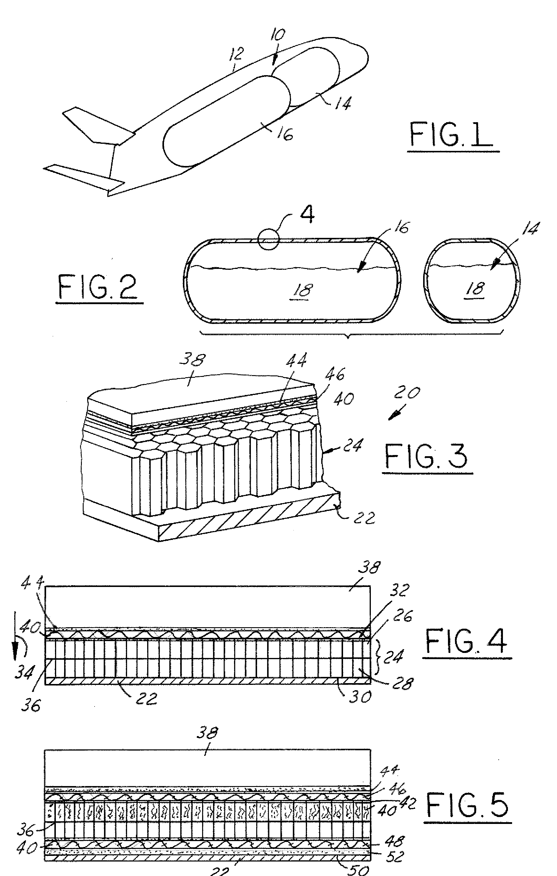
[0014] Referring now to FIG. 1, which is an illustration of the fuel tank assembly 10 in accordance with the present invention. The fuel tank assembly 10 is illustrated installed within an aerospace vehicle 12 such as a reusable launch vehicle (RLV). It should be understood that the fuel tank assembly 10 can be utilized in a wide variety of aerospace vehicles 12 and the vehicle shown is for illustrative purposes only. Similarly, the fuel tank assembly 10 is illustrated as comprising a forward fuel tank 14 and a rear fuel tank 16. It should be understood, however that the number and orientation of fuel tanks 14, 16 within the RLV 12 are contemplated to be application specific.

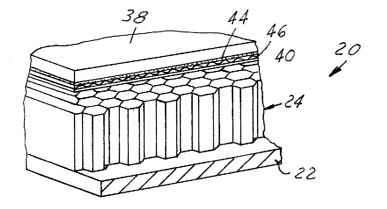
[0015] The fuel tank assembly 10 is intended to contain a cryogenic fuel supply 18 (see FIG. 2). The cryogenic fuel supply 18 must be thermally protected such that the fuel is kept within a temperature range suitable to prevent boil-off or phase change. The present invention provides a unique approach to mainta...


PUM

PropertyMeasurementUnit
impact resistanceaaaaaaaaaa
sizeaaaaaaaaaa
strengthaaaaaaaaaa

Abstract

A cryogenic fuel tank assembly 10 is provided comprising a cryogenic fuel tank wall 22. A foam assembly 24 is affixed to the cryogenic fuel tank wall 22, the foam assembly 24 having an inner surface 30 and an outer surface 32. A first solid film 40 bonded to the outer surface 32 to provide a uniform outer bonding surface 42. A thermal protection system assembly 38 is bonded to the uniform outer bonding surface 42.

Description

BACKGROUND OF INVENTION [0001] The present invention relates generally to an insulation assembly for use with cryogenic fuel tanks and more specifically to an insulation assembly having improved bonding characteristics. [0002] Aerospace vehicle designs commonly utilize a variety of fuels to supply both launch and maneuvering power requirements. The quantity of fuel required for most missions, especially for launch requirements, often generates severe design constraints and can require considerable portions of vehicle size to be dedicated towards the carrying of fuel. The use of cryogenic fuels allows the fuels to be maintained in a liquid state rather than in their roomtemperature gaseous form. This allows a greater quantity of fuel to be stored in a smaller container. This, in turn, improves the design capabilities of aerospace vehicles. [0003] Current cryogenic fuel tank technology for expendable launch systems such as the external tank of the space shuttle use spray-on foam insul...

Claims


Application Information

Patent Timeline
Patent Type & Authority Applications(United States)
IPC IPC(8): B64C1/00B64D37/06B64G1/14B64G1/40F17C13/00
CPCB64D37/06B64G1/14B64G1/402F17C13/001Y02T90/44F17C2201/0109Y10T428/1376F17C2203/0333F17C2223/0161F17C2223/033F17C2260/033F17C2270/0189F17C2201/056Y02T90/40
Inventor HOGENSON, PETER A.CHONG, KEITHDUONG, PETER
Owner THE BOEING CO
Why Eureka
Try Eureka