Methods and systems for medical imaging

a medical imaging and system technology, applied in the field of medical imaging systems, can solve the problems of slow ultrasound system obtained and display of three-dimensional volume, limited time and space presentation of such images, and inability to display

Active Publication Date: 2005-04-28
GE MEDICAL SYST GLOBAL TECH CO LLC
View PDF8 Cites 79 Cited by
  • Summary
  • Abstract
  • Description
  • Claims
  • Application Information

AI Technical Summary

Problems solved by technology

In the past, however, the time and space presentation of such images has been limited because of the time-consuming processing (including firing ultrasound beams, receiving the beams, and beamforming) associated with generating the images.
While it would be beneficial in many instances for a doctor to view a rapid or real-time image sequence of a three dimension region over a significant section of anatomy, such display has typically not been possible.
Generally, as the size or resolution of the three dimensional volume showing the region is increased, the slower the ultrasound system obtained and displayed the three dimensional volume.
However, at the point where the ultrasound system could acquire and display three dimensional volumes in real-time, the anatomical region that was imaged was too small in size or resolution to be diagnostically useful.
Thus, prior ultrasound systems were limited to slowly displaying large regions or high resolutions, or quickly displaying small regions (without sufficient content) or low resolutions quickly.
In other words, in three dimensional imaging in particular, there was al limit to how large of an image could be acquired and displayed in real-time with sufficient resolution in time and space while presenting clinically relevant data.
Due to both system limitations and physical limitations related to the speed of sound, only a limited number of ultrasound lines can be acquired simultaneously.
With these restrictions it is only possible to acquire a limited volume with any rapidity.
However, this technique suffers from a significant drawback in that the display of the full image is done only after the acquisition of all of the sub-volumes.
Thus, the doctor or technician performing the acquisition only obtains limited diagnostic information during acquisition.

Method used


Image

  • Methods and systems for medical imaging
  • Methods and systems for medical imaging
  • Methods and systems for medical imaging

Examples


Embodiment Construction

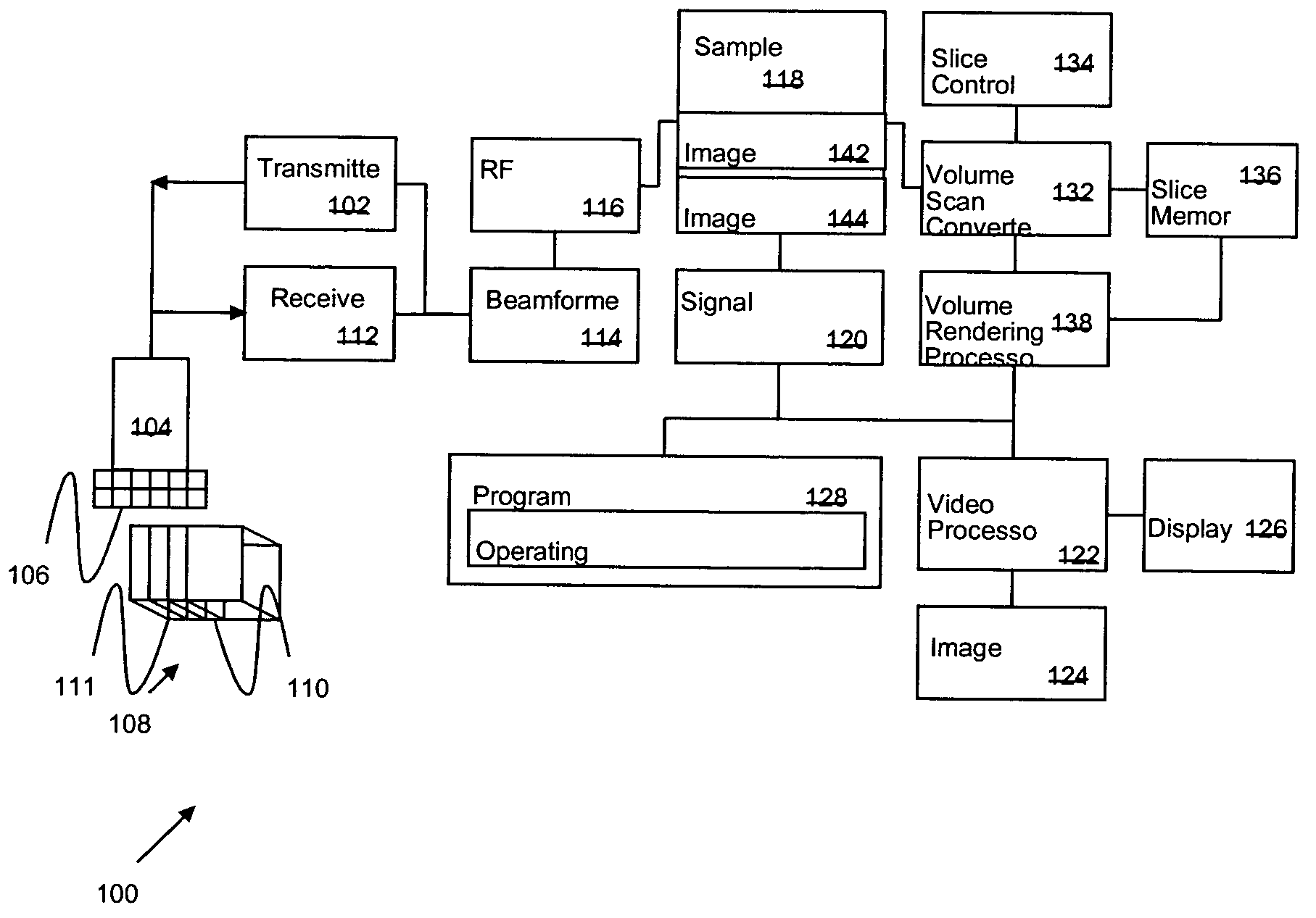
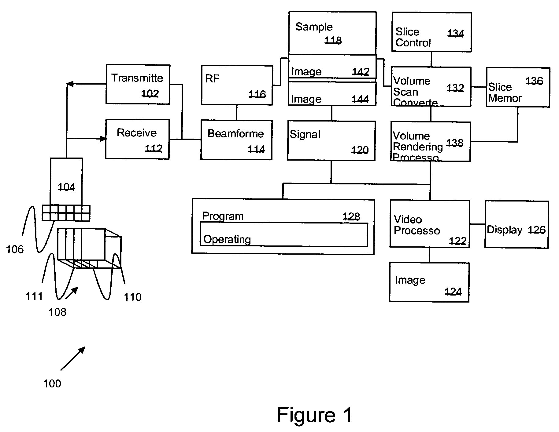
[0016] Before turning in detail to the image display and acquisition techniques and systems, an exemplary ultrasound imaging system suitable for using the techniques is summarized with reference to FIG. 1. The invention is not limited to use with ultrasound systems, however, and may instead find use in a wide variety of imaging systems in which physiologic structure is displayed, including X-ray systems, fluoroscopic systems, and so forth.

[0017]FIG. 1 illustrates a diagram of the functional blocks of an ultrasound system 100. The functional blocks are not necessarily indicative of the division between hardware circuitry. Thus, for example, one or more of the functional blocks (e.g., processors or memories) may be implemented in a single piece of hardware (e.g., a general purpose signal processor or a block or random access memory, hard disk, and so forth). Similarly, the programs may be separate stand alone programs or routines in a single program, may be incorporated as functions ...


PUM


Abstract

A medical imaging system includes an image sensor that receives imaging signals from a region of interest, a memory coupled to the image sensor, and a processor coupled to the memory. The memory stores image data derived from the imaging signals for first and second sub-regions of the region of interest acquired during a first and second occurrence of a physiologic cycle. The processor initiates display of the first image data while the second image data is being acquired and initiates display of the first image data joined with the second image data after the second image data is acquired.

Description

BACKGROUND OF THE INVENTION [0001] This invention relates generally to medical imaging systems. More specifically, this invention relates to real time display of complex medical images obtained with a medical imaging system. [0002] Doctors and technicians commonly employ medical imaging systems to obtain, display, and study images for diagnostic purposes. In ultrasound imaging systems, for example, a doctor may obtain heart images in an attempt to learn whether the heart functions properly. In recent years, these imaging systems have become very powerful, and often include the capability to display a looping series of ultrasound images. [0003] The looping series of images appears to the viewer as a short repeating movie or video of the internal structures imaged during a series of ultrasound firings. In a cardiology examination, for example, the imaging system may capture ultrasound images of the heart. In the past, however, the time and space presentation of such images has been li...

Claims


Application Information

Patent Timeline
Patent Type & Authority Applications(United States)
IPC IPC(8): A61B8/00A61B8/13G01S7/52G01S15/89G06T7/00
CPCA61B8/13A61B8/463A61B8/543A61B8/483G01S15/8993G06T7/0012Y10S128/916G01S7/52034
Inventor STEEN, ERIK NORMANN
Owner GE MEDICAL SYST GLOBAL TECH CO LLC
Why Eureka
Try Eureka