
Transformation of a Three-Dimensional Flow Image

Inactive Publication Date: 2014-06-12
ISIS INNOVATION LTD
View PDF1 Cites 8 Cited by
  • Summary
  • Abstract
  • Description
  • Claims
  • Application Information

AI Technical Summary

Benefits of technology

The patent describes a method for studying the flow of blood in subjects such as placentas and uteruses. This is done by flattening the surface of a three-dimensional flow image into a two-dimensional flow image. This transformation makes it easier to understand and extract information from the flow image. The method can also be used to study the flow at a variety of locations by generating a set of consistent two-dimensional flow images. This simplifies the analysis of the flow data and makes it easier to investigate the information of interest. The technical effect of this method is improved understanding and analysis of blood flow in subjects, which can be useful in clinical practice.

Problems solved by technology

However, in many applications, the visualisation and understanding of the flow is complicated and from the resultant three-dimensional flow images it can be difficult to extract useful information, for example clinically significant information in the case of a biomedical study.
Besides being time consuming, both these approaches have their drawbacks as neither approach is a direct measurement of the site of the pathology.
A manual segmentation as disclosed in Reference 2 is problematic in that quantification of a 3D ultrasound Doppler signal in the placenta and uterus is difficult because the organ is unique in having two independent vascular systems, that is one from the mother and the other from the fetus.
Thus, with both of the approaches, it is difficult to extract clinically significant information.
Similar difficulties of extracting useful information exist in the use of types of three-dimensional flow image other than an ultrasound Doppler image.

Method used


Image

  • Transformation of a Three-Dimensional Flow Image
  • Transformation of a Three-Dimensional Flow Image
  • Transformation of a Three-Dimensional Flow Image

Examples


Embodiment Construction

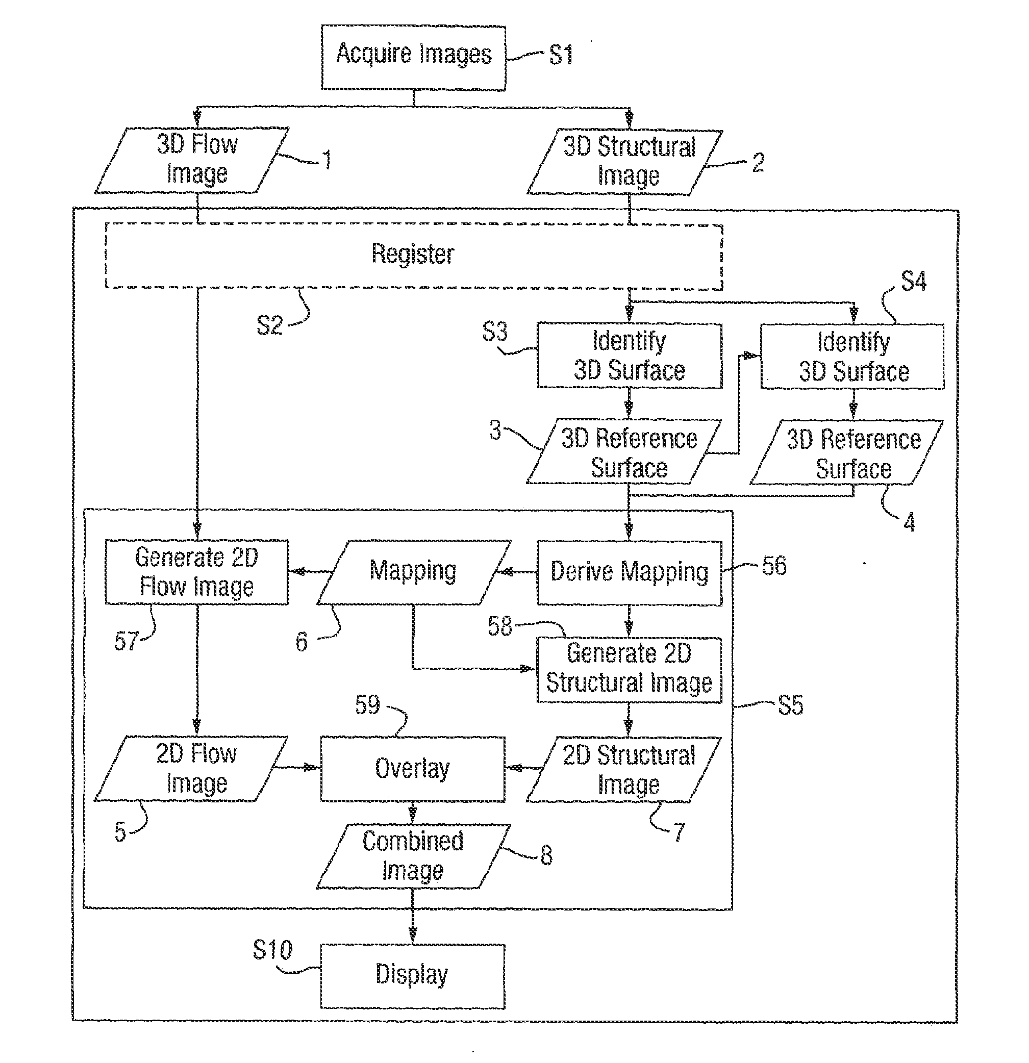
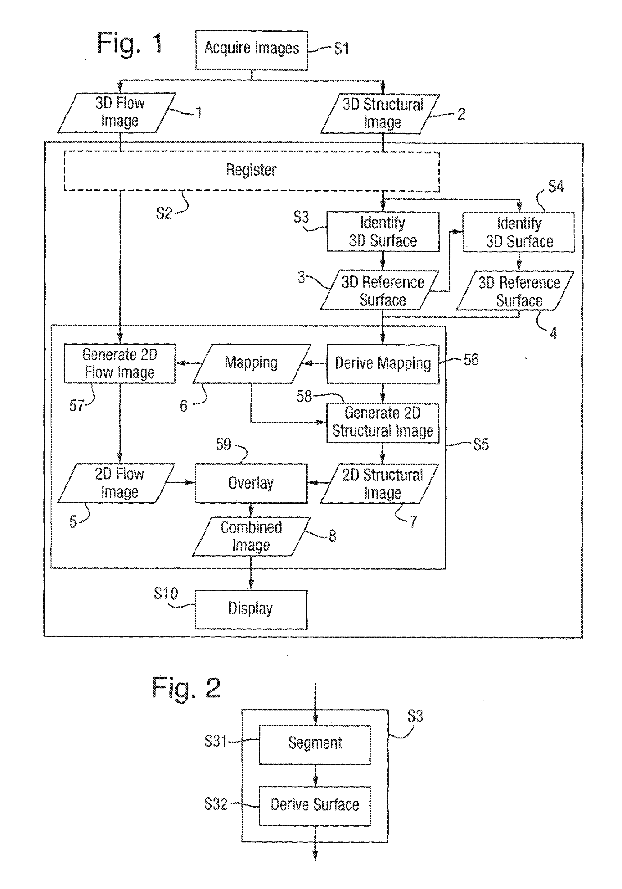
[0037]FIG. 1 shows a method of acquiring and transforming a three-dimensional (3D) flow image 1, in which a three dimensional structural image 2 is also acquired and used.

[0038]In step 1, a subject is imaged to acquire the 3D flow image 1 and the 3D structural image 2, each comprising a set of values for respective voxels (3D pixels) in a field of view. The 3D flow image 1 represents flow within the subject. The 3D structural image 2 has a common field of view with the 3D flow image 1 and represents structure within the same subject.

[0039]Any type of imaging technique that acquires the 3D flow image 1 and the 3D structural image 2 may be used. Step S1 may be performed using known techniques with appropriate imaging apparatus.

[0040]One type of imaging technique that may be applied to both the 3D flow image 1 and the 3D structural image 2 is ultrasonography. In this case, the 3D flow image 1 is an ultrasound intensity image, in which the image data represents the intensity of the meas...


PUM


Abstract

A method of transforming a three-dimensional ultrasound Doppler image that represents flow within a subject uses a three-dimensional ultrasound intensity image that has a common field of view and represents structure within the subject. Within the three-dimensional structural image, there is identified a three-dimensional reference surface that represents the location of a surface of the structure represented by the three-dimensional structural image. A mapping is derived that maps the three-dimensional surface into a two-dimensional plane. The mapping is applied to map the three-dimensional surface of the flow image at the location represented by the three dimensional reference surface into a two-dimensional flow image.

Description

CROSS-REFERENCES TO RELATED APPLICATIONS[0001]This application is a continuation of International Application No. PCT / GB2012 / 000077, filed Jan. 25, 2012, which is incorporated by reference in its entirety for all purposes.BACKGROUND OF THE INVENTION[0002]The present invention relates generally to imaging that provides a three-dimensional flow image that represents flow within a subject under investigation, and in particular to processing of a three-dimensional flow image.[0003]There are known imaging techniques that provide a three-dimensional flow image that represents flow within a subject under investigation, for example Doppler ultrasonography in which ultrasound Doppler signals are measured to provide an ultrasound Doppler image. Flow is of interest in many subjects. For example, in a biomedical study, a subject that is part of a human may be imaged to study flow, typically of blood, that provides information of clinical interest. However, in many applications, the visualisatio...

Claims


Application Information

Patent Timeline
IPC IPC(8): G06T15/00
CPCG06T15/00A61B8/06A61B8/0866A61B8/488A61B8/5261G06T17/00G06T19/00G06T2210/41G06T2219/021
Inventor STEVENSON, GORDONCOLLINS, SALLYNOBLE, JULIA ALISON
Owner ISIS INNOVATION LTD
Learn More