Although the shell of a paintball is ideally a
spheroid having a
diameter of 0.68 inches, in practice, paintballs are never truly spherical and have varying diameters.
It must not only provide sufficient
structural integrity to withstand firing from the pneumatic gun without breaking, it must, at the same time, be sufficiently fragile to permit fracture upon
impact with the target, even when the target absorbs some of the energy of the
impact.
Increased shell strength, while decreasing the risk of paintball breakage in the gun, decreases the likelihood of marking the target and also increases the risk of personal injury to paintball participants.
Higher temperatures increase the flexibility of the shell, while lower temperatures cause it to become more brittle.
As a result, paintballs exhibit significant shape deformations in response to
physical stress, such as that caused by the
impact of the compressed gases during launching.
Additionally, the fluid and air within the paintball are prone to expansion and contraction in response to changes in ambient temperature and
humidity.
), the clearance between the paintball and the inner walls of the barrel affects both distance and accuracy.
A barrel that is too loose will allow gas to escape around the paintball and will therefore be inefficient in imparting energy from the compressed gas to the paintball.
On the other hand, a barrel that is too tight around a paintball will create drag on the paintball, thereby slowing it down and preventing it from reaching its desired velocity.
Furthermore, excessive drag or gripping between the paintball and the barrel bore increases the probability of shell rupture within the barrel.
This goal cannot be acheived, however, if the paintball is manufactured with such strength and rigidity as to maintain a constant
diameter in the face of ambient environmental factors and launching stress.
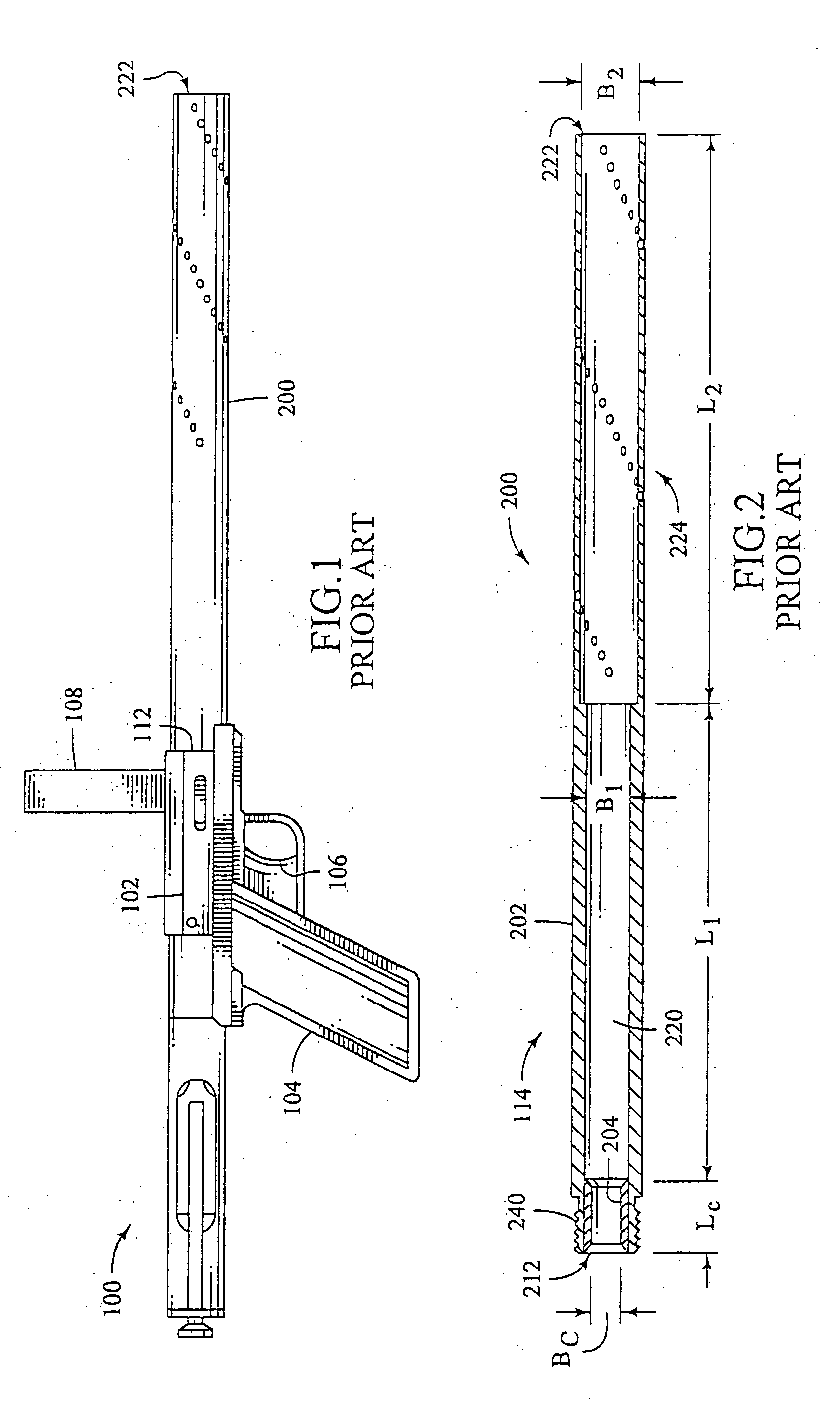
This prior art method is unattractive to the Paintball enthusiast for several reasons.
Their length and weight makes it awkward and uncomfortable to carry multiple barrels, especially during a paintball competition when the participant must perform athletic movements, such as crouching, leaping,
crawling, or rolling on the ground.
Furthermore, because stealth is often important in paintball matches, carrying multiple barrels may produce undesirable
noise by contacting other hard objects in the users pack.
Lastly, most barrels are fairly expensive-running anywhere between fifty dollars to well over an hundred dollars-making acquiring several barrels a costly proposition, especially for the recreational player.
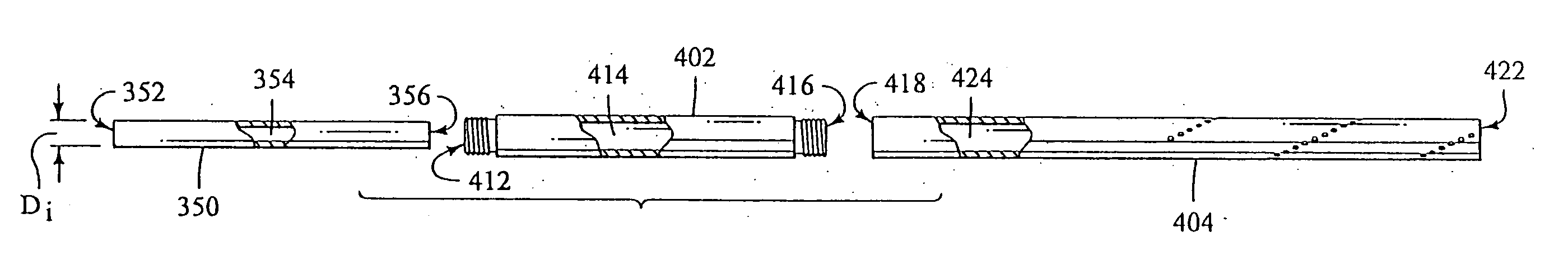
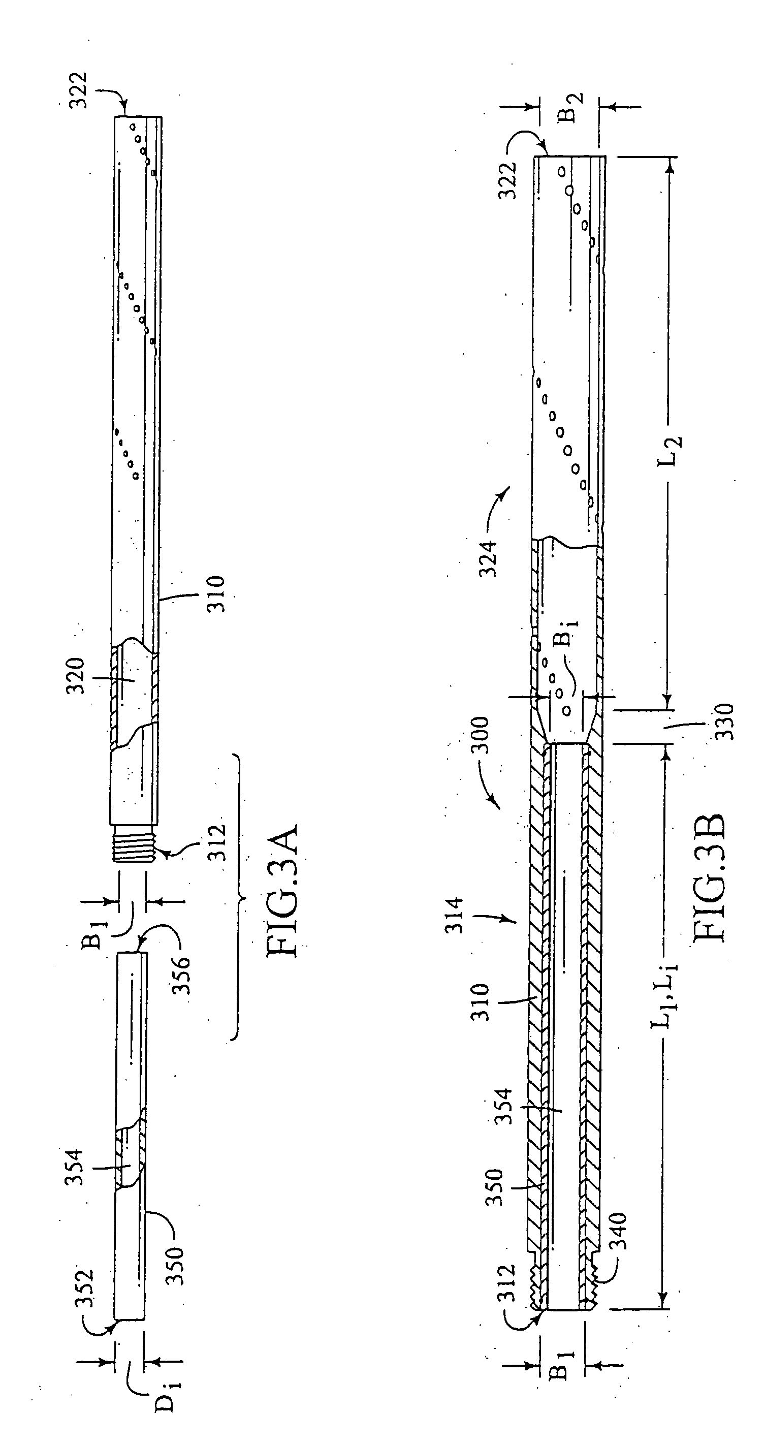
Although these interchangeable chokes provide a tight-fitting entrance for paintballs of various diameters to enter into the barrel, they are relatively short and extend only slightly into the breech end of the barrel.
They therefore fail to sufficiently stabilize the paintball trajectory and do not provide efficient transfer of energy from the compressed gas to the paintball.

