Fluid heater

Active Publication Date: 2005-05-05
HEISE LORNE
View PDF16 Cites 5 Cited by
  • Summary
  • Abstract
  • Description
  • Claims
  • Application Information

AI Technical Summary

Benefits of technology

[0007] According to one aspect of the present invention there is provided a fluid conduit having a peripheral wall to define a flow passage and a pair of fluid capillaries extending along the wall. The capillaries are connected in series and secured to the wall. Fluid may then flow along one of

Problems solved by technology

For example, in a fluid conveying system such as a water supply system, there is a danger during cold weather that fluid in the conduit will freeze.
Moreover, such installations tend to be used intermittently due to their relative inefficiency and power consumption.
The heating effect obtained from this installation is however limited to the available length of the heating cable which becomes a limiting factor in some installations.
Moreover, the electrical system is prohibited in some environments such as sewers or drains that may contain methane because of the possibility of ignition of sewer gas.
There is also a reticence to use electric heating cables in some environments where the cable may be exposed, such as roof and gutter de-icing, where damaged cables may come in contact with water and can result in fire when breakdown occurs.
Proper electrical installation ensures the safe operation of such devices but nevertheless there is always a risk of improper installation.

Method used


Image

  • Fluid heater
  • Fluid heater
  • Fluid heater

Examples


Embodiment Construction

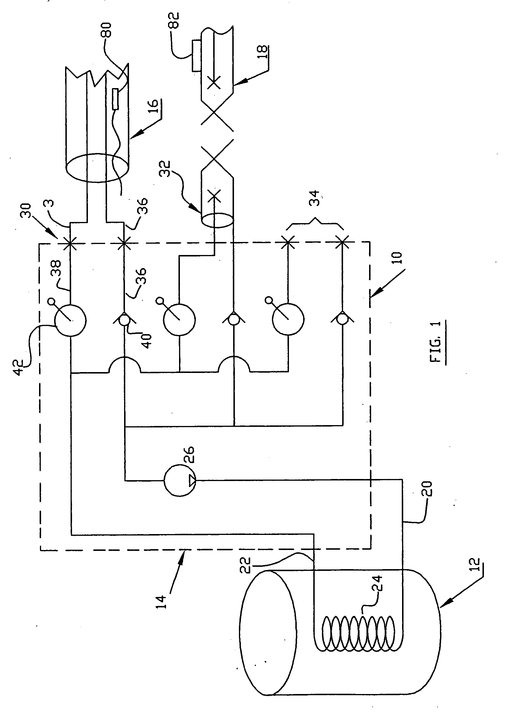
[0017] Referring therefore to FIG. 1, a heat distribution system 10 includes a fluid heater 12, a central manifold 14 and a pair of heat distribution apparatus 16, 18 connected at respective locations to the manifold 14. It will be appreciated that a cooling effect can be obtained using a fluid cooler rather than a heater but for ease of description reference will be made to the apparatus functioning as a heater.

[0018] The fluid heater 12 is connected to the manifold 14 through a supply line 20 and a return line 22. The lines 20, 22 are connected through an inlet 21 and outlet 23 to a coil 24 within the heater 12. A heating source, such as a gas or electric heater, is supplied to the coil 24 so that fluid within the coil 24 is heated as it passes through the coil between the inlet 21 and outlet 23. Fluid is circulated through the coil 24 by a pump 26 located within the manifold 24 and connected to the supply line 20. The lines 20, 22 are connected to each of a series of outlets 30,...


PUM


Abstract

A heat distribution apparatus comprising a fluid conduit having a peripheral wall defining a flow passage and a pair of fluid capillaries extending along the wall and secured thereto. The capillaries being connected to one another in series to provide a fluid flow path along one of the capillaries and a return path along another of said capillaries to convey heat exchange fluid to transfer heat between the flow passage and the heat exchange fluid.

Description

[0001] This application claims priority from U.S. Patent Application No. 60 / 507,127 filed on Oct. 1, 2003.FIELD OF THE INVENTION [0002] The present invention relates to methods and apparatus for distributing heat to or removing heat from remote locations. DESCRIPTION OF THE PRIOR ART [0003] It is often necessary to distribute heat to or remove heat from remote locations to inhibit freezing at that location. For example, in a fluid conveying system such as a water supply system, there is a danger during cold weather that fluid in the conduit will freeze. There are many proposals to supply heat to such a conduit such as by wrapping an electric heating cable about the conduit but these have tended to be used in locations close to. an electrical power source. Moreover, such installations tend to be used intermittently due to their relative inefficiency and power consumption. [0004] An alternate form of heating apparatus is shown in Canadian Patent 2019590 in which a self-regulating heat...

Claims


Application Information

Patent Timeline
IPC IPC(8): E03B7/12F24D19/00F28D7/00F28D7/10F28D7/16
CPCE03B7/12F28D7/0008F24D19/0095F16L53/002F16L53/32
Inventor HEISE, LORNE
Owner HEISE LORNE
Why Eureka
Try Eureka