Control of vehicle motor

a technology of electric motor and control panel, which is applied in the direction of electric energy management, special data processing applications, gas pressure propulsion mounting, etc., can solve the problems of increasing power consumption and inability to start the engine immediately, and achieve the effect of avoiding the delay in the startup tim

Inactive Publication Date: 2005-05-05
NISSAN MOTOR CO LTD
View PDF6 Cites 16 Cited by
  • Summary
  • Abstract
  • Description
  • Claims
  • Application Information

AI Technical Summary

Benefits of technology

[0003] However, in this prior art, an electric motor which has a field winding is used to start the engine. For starting the engine, the motor outputs a torque by passing an armature current after sufficient magnetic flux is generated by supplying an exciting current first to the field winding. Therefore, as the required motor torque is not outputted until the magnetic flux is fully developed after the exciting current starts to be supplied, the engine cannot be started immediately even if the idle stop release condition is satisfied. To eliminate the startup time delay, a steady current may be supplied to the field winding even during motor stop, but in this case power consumption will increase.
[0004] It is therefore an object of this invention to provide a motor control device which enables a motor to generate a required drive torque with a rapid response to a start request, and thereby prevent an increase in power consumption.

Problems solved by technology

Therefore, as the required motor torque is not outputted until the magnetic flux is fully developed after the exciting current starts to be supplied, the engine cannot be started immediately even if the idle stop release condition is satisfied.
To eliminate the startup time delay, a steady current may be supplied to the field winding even during motor stop, but in this case power consumption will increase.

Method used


Image

  • Control of vehicle motor
  • Control of vehicle motor
  • Control of vehicle motor

Examples


Embodiment Construction

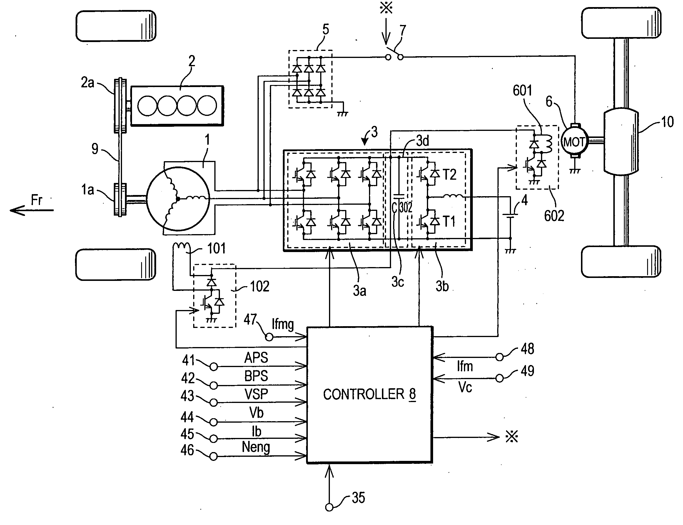
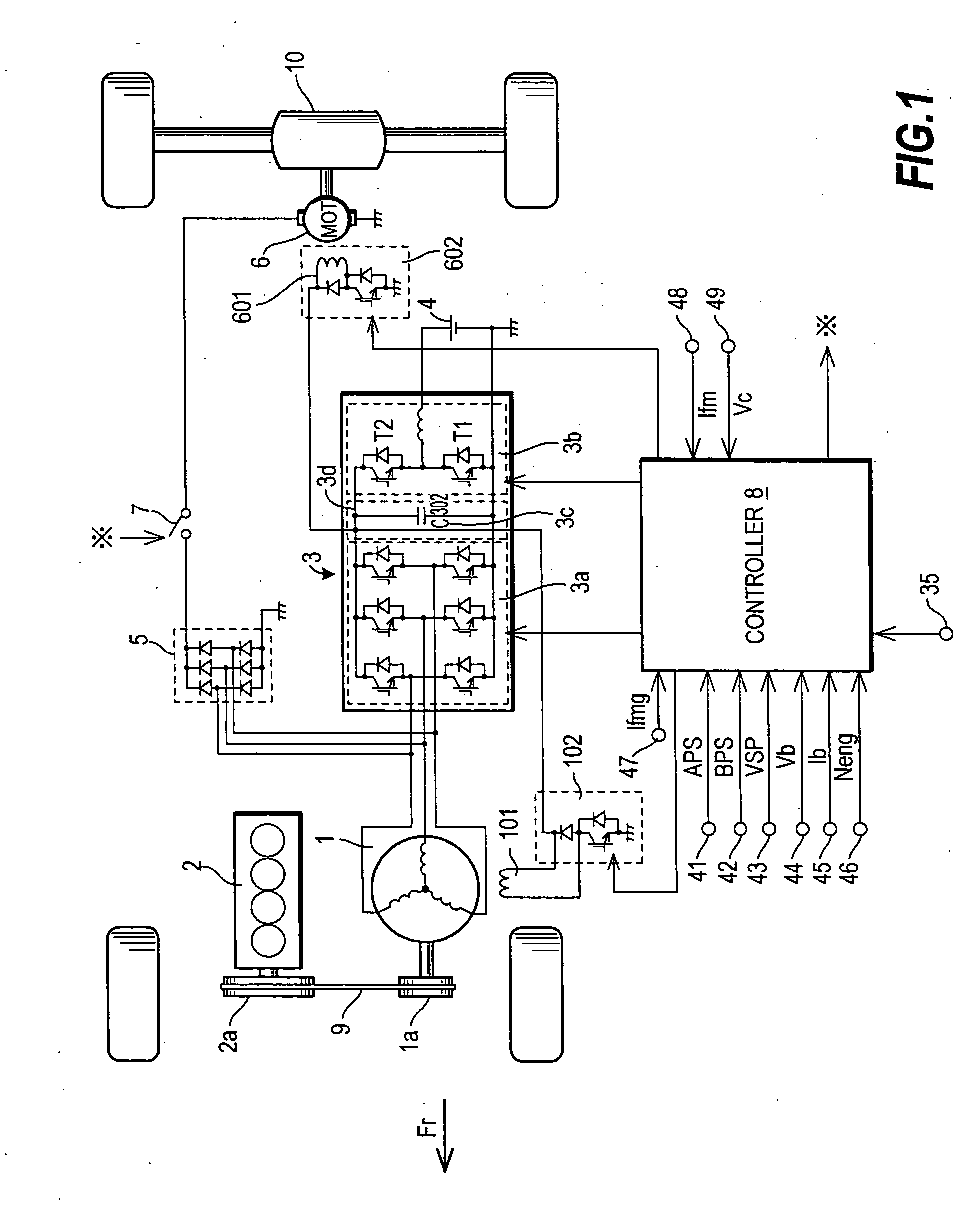
[0012] Referring to FIG. 1, the construction of a hybrid vehicle using this embodiment will first be described.

[0013] The hybrid vehicle has front wheels driven by the output torque from the engine 2, and rear wheels rotated by the output torque from a drive motor 6. The rear wheels are mainly driven during start acceleration and when the front wheels slip. The hybrid vehicle has an idle stop function which stops the engine automatically when predetermined conditions are satisfied (for example, during a traffic signal stop).

[0014] The hybrid vehicle has a startup motor 1, engine 2, voltage increase / decrease inverter 3, battery 4, diode circuit 5, drive motor 6, switch 7 and controller 8. The startup motor 1 has a field winding and an armature. The field winding generates magnetic flux (magnetic field) by being supplied with exciting current. An alternating current is supplied to the armature of the startup motor 1 as an armature current. A rotor of the startup motor 1 rotates due ...


PUM


Abstract

A motor control device for controlling an electric motor (1,6) installed in a vehicle, is disclosed. The motor has a field winding (101,601). The motor control device has a battery (4) charged by power at a first voltage (Vb), an voltage increase / decrease inverter (3) capable of increasing the first voltage from the battery, an excitation control circuit (102, 106) which allows or disallows supply of the exciting current to the field winding (101,601), a sensor (35,41-48) which detects a state of the vehicle, and a controller (8). The controller (8) determines whether or not to start the motor (1,6) based on a signal from the sensor (41-48). When the motor is to be started, the controller (8) allows supply of exciting current by the excitation control circuit (102, 106) and controls the voltage increasing circuit so that the first voltage is increased to a second voltage higher than the first voltage (Vb).

Description

FIELD OF THE INVENTION [0001] This invention relates to control of a vehicle electric motor. BACKGROUND OF THE INVENTION [0002] One type of hybrid vehicle performs an idle stop control which automatically stops and starts an engine for the purpose of improving fuel cost-performance performance or exhaust performance. Tokkai 2001-355480 published by the Japanese Patent Office in 2001 discloses such a hybrid vehicle. The hybrid vehicle of the prior art performs an idle stop, when predetermined conditions are satisfied during vehicle stop, and starts the engine automatically by a motor when an idle stop release condition holds. SUMMARY OF THE INVENTION [0003] However, in this prior art, an electric motor which has a field winding is used to start the engine. For starting the engine, the motor outputs a torque by passing an armature current after sufficient magnetic flux is generated by supplying an exciting current first to the field winding. Therefore, as the required motor torque is ...

Claims


Application Information

Patent Timeline
Patent Type & Authority Applications(United States)
IPC IPC(8): B60L15/20B60K6/20B60K6/26B60K6/28B60K6/44B60K6/46B60K6/52B60L50/10B60L50/15B60L50/16B60W10/06B60W10/08B60W20/00F02D17/00F02D29/02F02N11/04F02N11/08F02N15/00H02M7/48H02P27/06
CPCB60K6/52Y02T10/6265B60L11/14B60W10/06B60W10/08B60W20/00F02D2041/2044F02N11/0814F02N11/0859F02N11/0866F02N2011/0885F02N2011/0896F02N2200/044Y02T10/6286Y02T10/7077Y02T10/7258Y02T10/48B60L11/12B60L50/15B60L50/16F02N2011/0888Y02T10/40Y02T10/62Y02T10/70Y02T10/7072Y02T10/72B60L15/20B60W20/13
Inventor NAGAYAMA, KAZUTOSHI
Owner NISSAN MOTOR CO LTD
Why Eureka
Try Eureka