

Pseudodynamic off-chip driver calibration
- Summary
- Abstract
- Description
- Claims
- Application Information
AI Technical Summary
Benefits of technology
Problems solved by technology
Method used
Image

Examples
Embodiment Construction
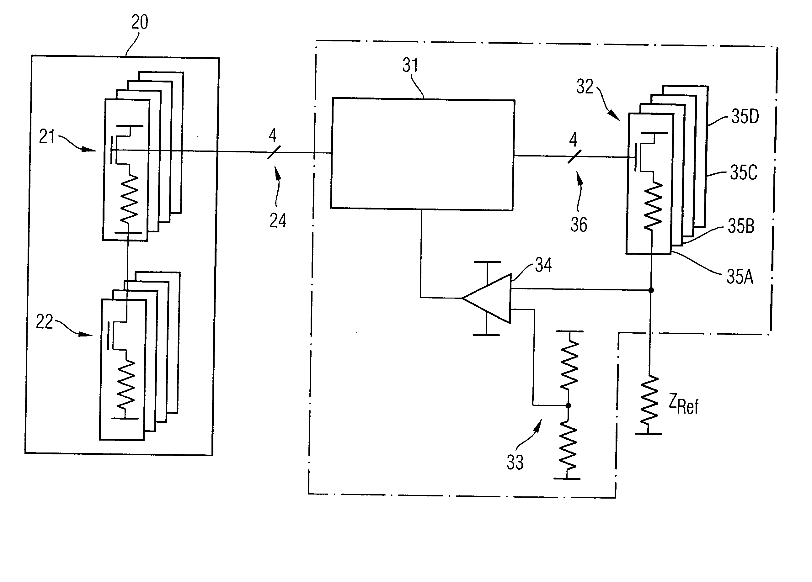
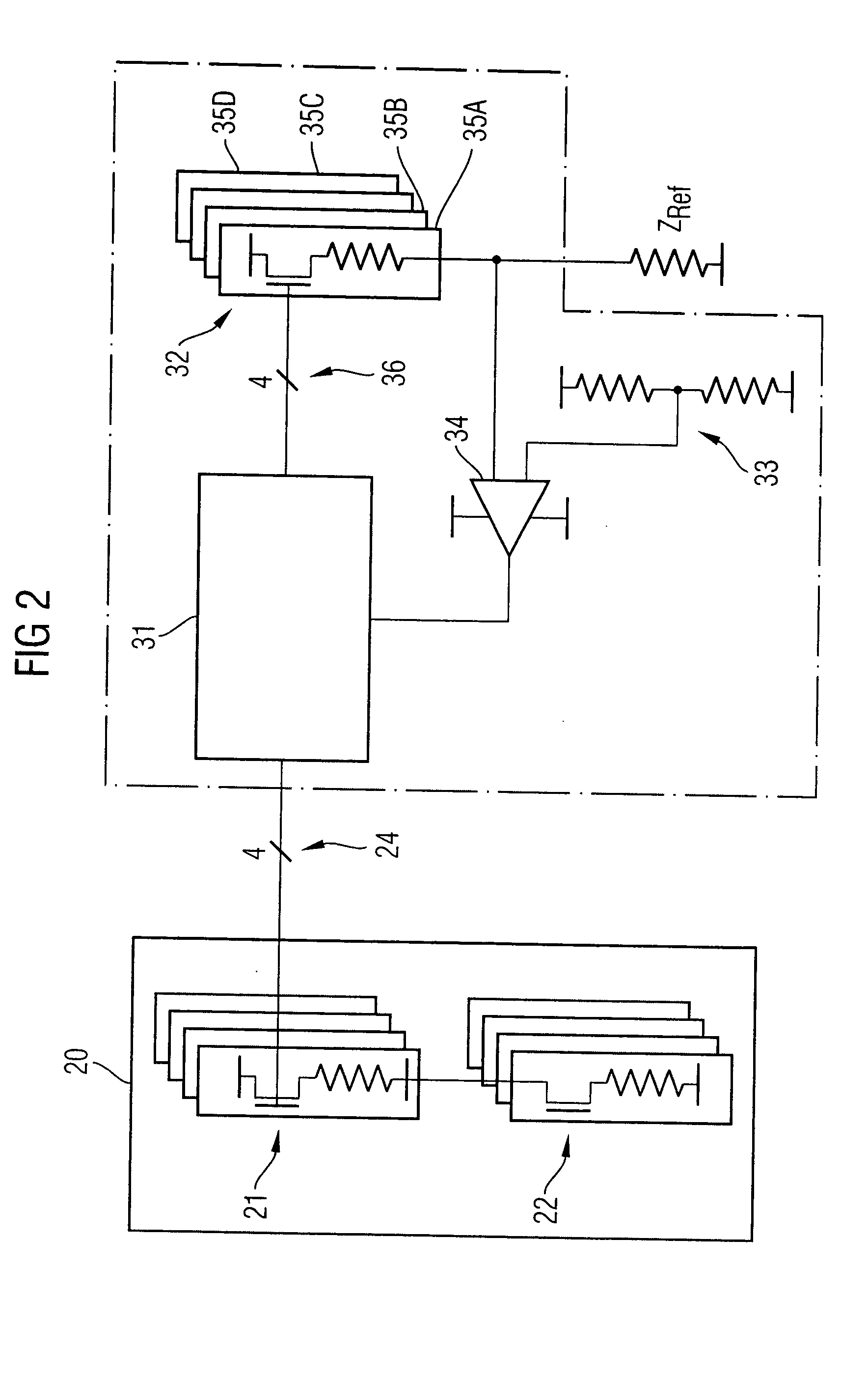
[0053]FIG. 2 shows a driver calibration circuit arrangement 30 according to a first exemplary embodiment of the invention, together with a driver circuit arrangement 20, illustrated schematically. The illustration shows a driver calibration circuit arrangement 30, which has a monitoring device 31, a variable impedance 32, a reference voltage divider 33, a comparator 34, and control lines 36. The driver calibration circuit arrangement 30 is connected to a reference impedance ZRef and to the driver circuit arrangement 20. The latter connection is made via a control line 24 which, for example, has four conductors. The variable impedance 32 comprises two or more switchable impedances 35A-D, which can be switched on and off via the control lines 36. The driver circuit arrangement 20 has a pull-up branch 21 and a pull-down branch 22, whose respective impedance can be influenced via the control line 24.
[0054] Together with the reference impedance ZRef, the variable impedance 32 forms a vo...
PUM
 Abstract
Description
Claims
Application Information