Combined Bragg grating wavelength interrogator and brillouin backscattering measuring instrument

a wavelength interrogator and brillouin technology, applied in instruments, borehole/well accessories, surveys, etc., can solve the problems of high cost and complexity of dedicated instruments for sensing both bragg grating and brillouin based measurements

Active Publication Date: 2005-05-05
WEATHERFORD TECH HLDG LLC
View PDF10 Cites 77 Cited by
  • Summary
  • Abstract
  • Description
  • Claims
  • Application Information

AI Technical Summary

Benefits of technology

[0007] In another embodiment, an apparatus for sensing an attribute in returning optical signals includes a Bragg grating sensor coupled by an optical fiber to a light source and signal detection circuit. The light source is suitable for producing optical signals tunable over a range of wavelengths and is adapted to generate a signal having sufficient intensity to produce Brillouin scattering of the signal while propagating in the optical fiber. The signal detection circuit includes a first sensing b

Problems solved by technology

Systems having dedicated instruments for sensing both Bragg grating

Method used


Image

  • Combined Bragg grating wavelength interrogator and brillouin backscattering measuring instrument
  • Combined Bragg grating wavelength interrogator and brillouin backscattering measuring instrument
  • Combined Bragg grating wavelength interrogator and brillouin backscattering measuring instrument

Examples


Embodiment Construction

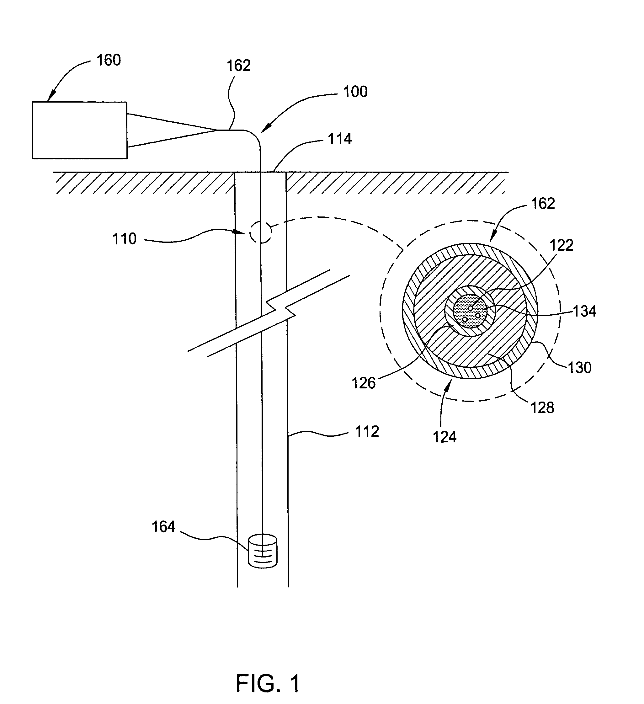
[0014]FIG. 1 is a simplified schematic of an oil or gas well 110 having an optical fiber sensing system 100 adapted to sense environmental conditions within the well 110 using a method and apparatus of the present invention. The well 110 includes a main bore 112 extending from a wellhead 114. The sensing system 100 utilizes both Bragg grating reflections and non-linear induced back scatter signals to resolve environmental conditions along the sensing path. In one embodiment, wavelengths and / or frequency of reflected signals are indicative of temperature and strain information of the environmental conditions within the well 110.

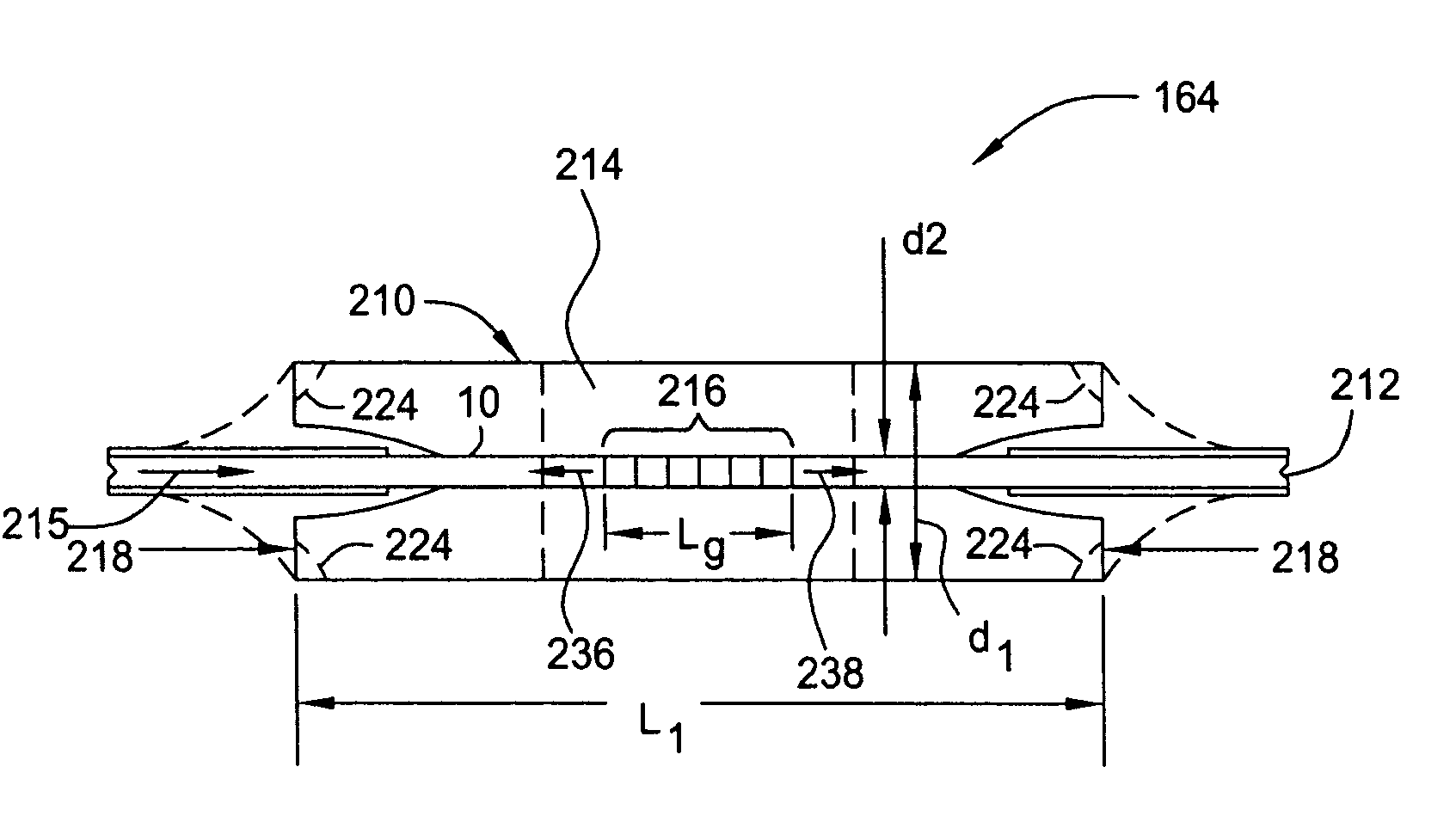
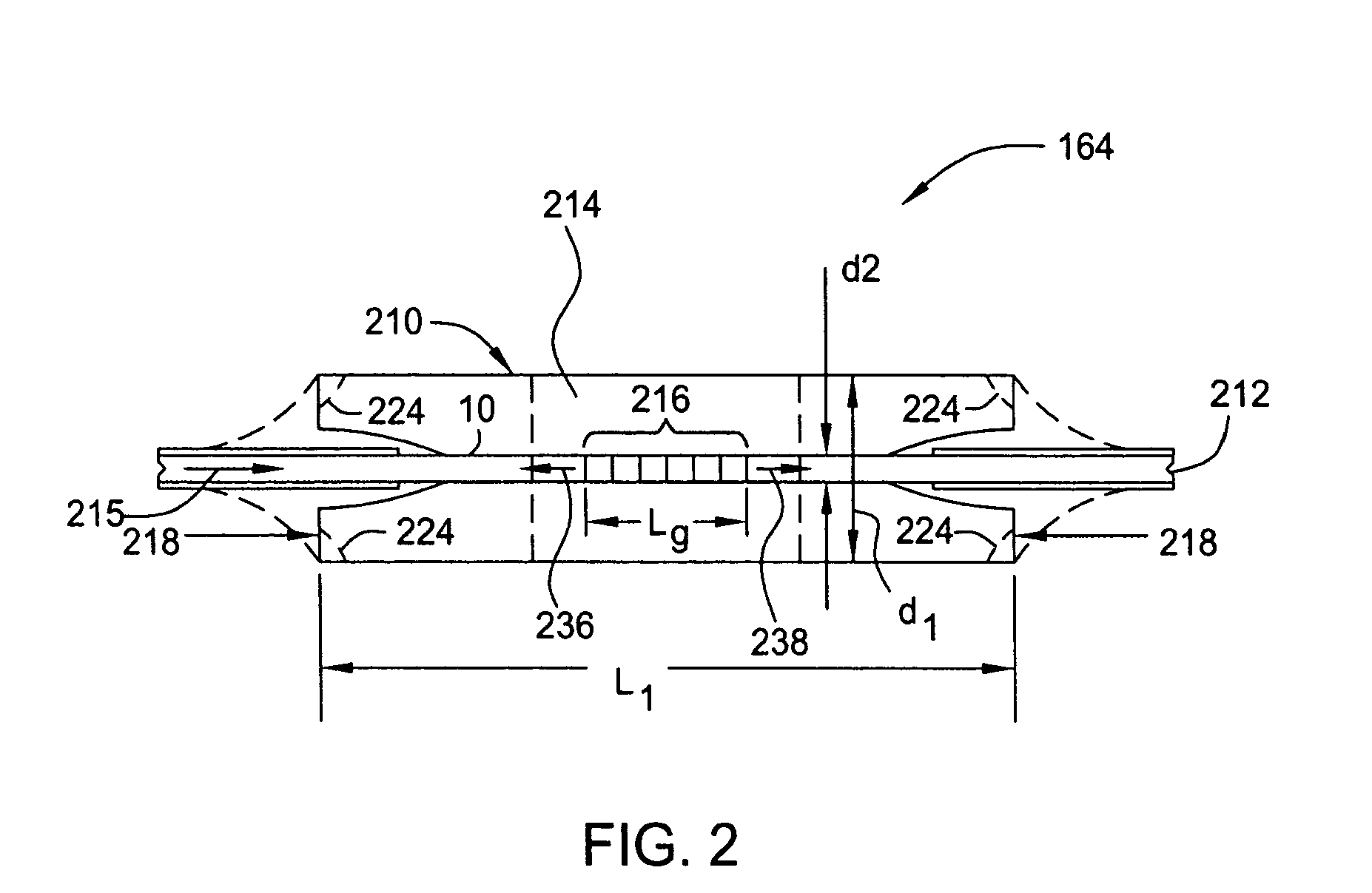
[0015] The sensing system 100 includes an interrogator 160 coupled by an optic cable 162 to at least one sensor 164. The sensor 164 may be a single point sensor or other suitable Bragg grating sensor. One sensor 164 that may be utilized is available from Weatherford, Inc., located in Houston, Tex. Another example of a sensor 164 that may be utilized is descri...


PUM


Abstract

A method and apparatus for sensing attributes of reflected signals in an optical fiber sensing system is provided. In one embodiment, a method for sensing in an optical fiber sensing system comprising an interrogator coupled to a Bragg grating sensor by an optical cable includes the steps of producing a first optical signal, coupling the first optical signal to an optical cable, receiving a first reflected signal from a Bragg grating sensor within the optical cable, resolving a wavelength of first reflected signal, producing a second optical signal, coupling the second optical signal to the optical cable, receiving a second reflected signal caused by Brillouin backscattering within the optical cable, and resolving a difference in frequencies between the second optical signal and second reflected signal. Embodiments of the method and apparatus are particularly useful for sensing temperature and strain in hazardous locations such as down hole gas and oil field applications and the like.

Description

BACKGROUND OF THE INVENTION [0001] 1. Field of the Invention [0002] Embodiments of the invention generally relate to a method and apparatus for detecting changes in a reflective signal in a fiber optic sensing system. [0003] 2. Background of the Related Art [0004] For fiber optic sensing systems, specifically Bragg grating-based systems, a dedicated opto-electronic instrument is required to measure environmentally-induced changes in peak wavelengths. If additional measurements, such as Brillouin-based temperature and / or strain measurements are needed, additional dedicated opto-electronic instrumentation is required. Systems having dedicated instruments for sensing both Bragg grating and Brillouin based measurements can be extremely costly and complex. [0005] Therefore, there is a need for an improved fiber optic sensing system. SUMMARY OF THE INVENTION [0006] A method and apparatus for sensing using an optical fiber are provided. In one embodiment, a method for sensing an attribute ...

Claims


Application Information

Patent Timeline
IPC IPC(8): E21B47/06G01D5/353G01K11/32
CPCE21B47/065G01K11/3206G01D5/35303E21B47/07G01D5/35316G01D5/35354G01D5/35358
Inventor MACDOUGALL, TREVOR
Owner WEATHERFORD TECH HLDG LLC
Why Eureka
Try Eureka