Lighting module for a vehicle headlight

a technology for vehicle headlights and light modules, which is applied in the direction of fixed installation, lighting and heating equipment, lighting support devices, etc., can solve the problems of difficult to produce a clean cut-off, significant part of the light flux emitted by the light source is dissipated in the rear face of the mask, and achieves the elimination of the use of masks, reducing the amount of light flux lost, and ensuring the effect of safety

Inactive Publication Date: 2005-05-05
VALEO VISION SA
View PDF2 Cites 35 Cited by
  • Summary
  • Abstract
  • Description
  • Claims
  • Application Information

AI Technical Summary

Benefits of technology

[0012] The present invention aims to provide a lighting module for a vehicle headlight which produces a lighting beam of the type having a cut-off and enabling a clean cut-off to be obtained, in particular by making use of a diode as light source, together with a homogeneous light beam, while at the same time offering a reduction in the amount of light flux lost, by eliminating the use of a mask.
[0022] In addition, the lighting module according to the invention enables a clean cut-off to be obtained, especially with a diode, because it projects the image of the cut-off edge forwards. The form of the cut-off in the lighting beam is therefore determined by the profile of the cut-off edge.
[0023] Another advantage of the module according to the invention is that it exploits a property of elliptical lighting modules which is that of “mixing” the images of the light source at the second focus of the first reflector, which improves the homogeneity of the lighting beam produced.
[0024] In addition, such a module has improved optical performance as compared with a system using a lens; in this connection, there are fewer losses due to the non-unitary coefficient of reflection of the reflective surfaces of the second and third reflectors than by reflections in glass within the lens.
[0025] Finally, with the configuration of the invention, the first reflector and its light source may be concealed behind one of the said second and third reflectors, so that the user, when looking at the output beam, does not see the first reflector. Such a solution does for example enable the use of a mask for the purpose of masking the first reflector and its light source to be eliminated.

Problems solved by technology

However, such a solution does have certain difficulties.
Thus, one disadvantage of this type of headlight is that a significant part of the light flux emitted by the light source is dissipated in the rear face of the mask.
This solution again has certain problems.
Thus, where the light source is a diode, it is very difficult to produce a clean cut-off.
In this connection, the image of the virtual source that corresponds to the diode is generally round and is diffuse, and it is far more complicated to produce a clean cut-off by aligning the corresponding images of round form.
This difficulty can be overcome by making use of a diaphragm with the diode, but a large quantity of the light energy produced by the diode is then lost.
In addition, those emission indicators of the diodes that are known to have the best performance are complex, and the production of a homogeneous beam is very difficult to obtain from direct images of the diode.

Method used


Image

  • Lighting module for a vehicle headlight
  • Lighting module for a vehicle headlight
  • Lighting module for a vehicle headlight

Examples


first embodiment

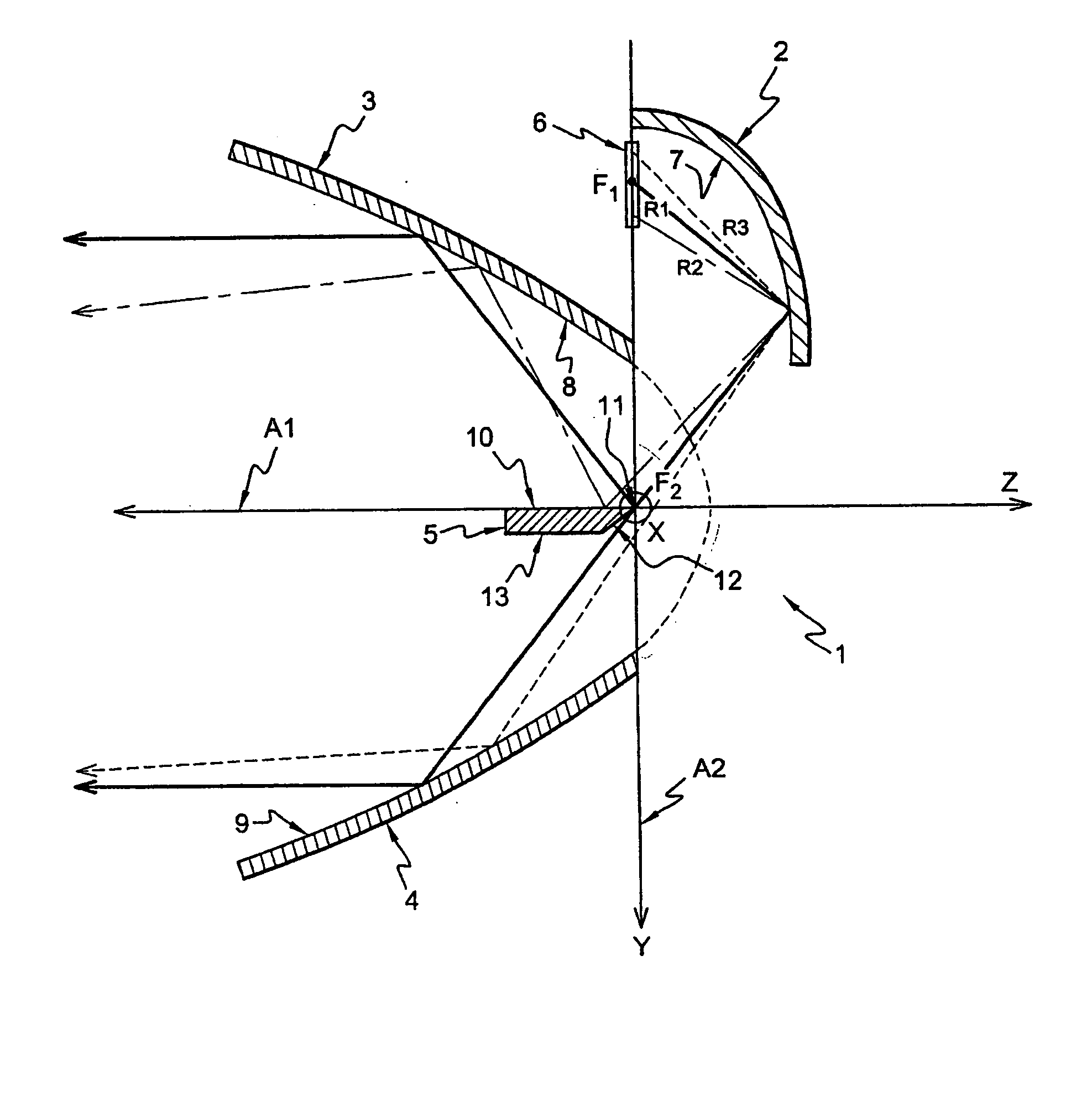
[0071]FIG. 1 shows diagrammatically a side view of a lighting module 1 for a vehicle headlight in the invention.

[0072] The module 1 comprises a first reflector 2, a second reflector 3, a third reflector 4, a fourth reflector 5, and a light source 6.

[0073] The second reflector 3 is an elliptical reflector having two foci F1 and F2, an optical axis A2, and a substantially elliptical reflective surface 7.

[0074] The substantially elliptical reflective surface 7 is made in the form of an angular sector of what is substantially a body of revolution, and lies in the half space which is situated above an axial plane at right angles to the plane of the page, this plane containing the optical axis A2. In a first approximation, the surface 7 is semi-elliptical.

[0075] However, it may be noted that the surface 7 may not be perfectly elliptical, and may have a plurality of specific profiles which are arranged to optimise the distribution of light in the light beam which is produced by the modu...

second embodiment

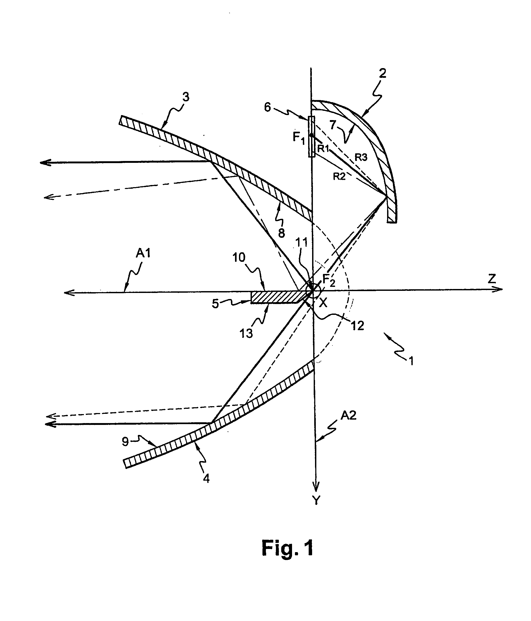
[0096]FIG. 2 shows diagrammatically a side view of a lighting module 100 for a vehicle headlight, in the invention.

[0097] The module 100 is identical to the module 1 in FIG. 1, except that it also includes a fifth reflector 14.

[0098] This fifth reflector has a reflective surface 15 which receives light rays directly from the light source 6 and produces a beam of light rays below the horizontal cut-off line. If the light source 6 were a point source and not surrounded by any optical apparatus, the reflective surface 15 would be a parabolic surface with a focus situated at the second focus F2 of the first reflector.

[0099] In practice, the light source 6, such as a light emitting diode, is not a point source, and it includes a chip, not shown, with a square or rectangular surface surrounded by a spherical half lens of plastics material, also not shown, which is centred on the centre of the chip. As a result, the non-point characteristics of the source and lens must be taken into cons...

third embodiment

[0107]FIG. 3 shows diagrammatically a side view of a lighting module 101 for a vehicle headlight, in the invention.

[0108] The module 101 is identical to the module 1 in FIG. 1, except that it further includes a reflector 18 referred to as a reflector without cut-off, and a second light source 20.

[0109] The reflector 18 without cut-off has an internal reflective surface 19 which is substantially parabolic, an optical axis coincident with the optical axis A1 of the second and third reflectors 3 and 4, and a focus F3.

[0110] The focus F3 is positioned positively on the axis F2-Z, and the light source 20 is arranged in the vicinity of the said focus F3.

[0111] If the reflective surface 19 of the reflector 18 without cut-off were a true parabola, it would produce a substantially circular output beam without any cut-off. Now, the regulating authorities require that functions not having any cut-off, of the main beam or DRL type, should have a beam which is about twice as wide as it is hig...


PUM


Abstract

The present invention relates to a lighting module for a vehicle headlight which produces a lighting beam of the type having a cut-off, and which is particularly well adapted for use with light emitting diodes. The module has a first reflector which includes an elliptical surface for reflecting light rays and having an elliptical generatrix, together with at least one first light source which is arranged in the vicinity of the first focus of the said first reflector. The module also includes: a second reflector, for producing a first portion of the cut-off beam and having an optical axis, which passes through the second focus of the first reflector and at right angles to the optical axis of the said first reflector; a third reflector producing a second portion of the cut-off beam and having an optical axis passing through the second focus of the said first reflector and at right angles to the optical axis of the said first reflector; and a fourth reflector or bender, which is arranged between the said second reflector and the said third reflector. The bender has an edge referred to as a cut-off edge, which is arranged close to the said focus of the said first reflector, in such a way as to form the cut-off in the lighting beam, together with a reflective top face which contains the said optical axes of the second and third reflectors respectively.

Description

FIELD OF THE INVENTION [0001] The present invention relates to a lighting module for a vehicle headlight, for producing a lighting beam of the cut-off type, which is, in particular, adapted for use with light emitting diodes. BACKGROUND OF THE INVENTION [0002] A lighting beam with cut-off is to be understood to mean a lighting beam which has a directional limit or cut-off line above which the intensity of the light emitted is weak. The functions of passing or dipped-beam lights, and anti-fog lights, are examples of light beams with cut-off in accordance with current European legislation. [0003] Generally, in an elliptical headlight, the cut-off is achieved by means of a mask, which is formed from a vertical plate the profile of which is suitably adapted, and which is interposed axially between the elliptical reflector and the convergent lens, the mask being arranged in the vicinity of the second focus of the reflector. [0004] The mask occults the light rays issued from the light sou...

Claims


Application Information

Patent Timeline
Patent Type & Authority Applications(United States)
IPC IPC(8): F21S8/10F21V7/00F21V7/09F21W101/10F21W107/10F21Y101/00
CPCF21S48/1159F21Y2101/02F21S48/1388F21S48/1163F21Y2115/10F21S41/155F21S41/321F21S41/323F21S41/43F21S41/60F21S41/663F21S43/14F21S43/31F21S41/365F21S41/145
Inventor ALBOU, PIERRE
Owner VALEO VISION SA
Why Eureka
Try Eureka