Data unit detection including antenna diversity

a data unit and antenna technology, applied in diversity/multi-antenna systems, polarisation/directional diversity, instruments, etc., can solve the problems of increasing the cost of the receiving device, if at all possible, and difficult reception

Inactive Publication Date: 2005-05-05
SHARP KK
View PDF85 Cites 28 Cited by
  • Summary
  • Abstract
  • Description
  • Claims
  • Application Information

AI Technical Summary

Problems solved by technology

With such a short wavelength the receiving device, such as a wireless telephone, may be periodically located in an unsuitable phase relationship with respect to the received signal.
In other words, the receiving device may be positioned at a location where the signal is at a minimum making reception difficult, if at all possible.
Unfortunately, including a pair of detection circuits 24a, 24b within the receiving device 20 consumes twice the power of a single detection circuit and increases the expense of the receiving device 20.

Method used


Image

  • Data unit detection including antenna diversity
  • Data unit detection including antenna diversity
  • Data unit detection including antenna diversity

Examples


Embodiment Construction

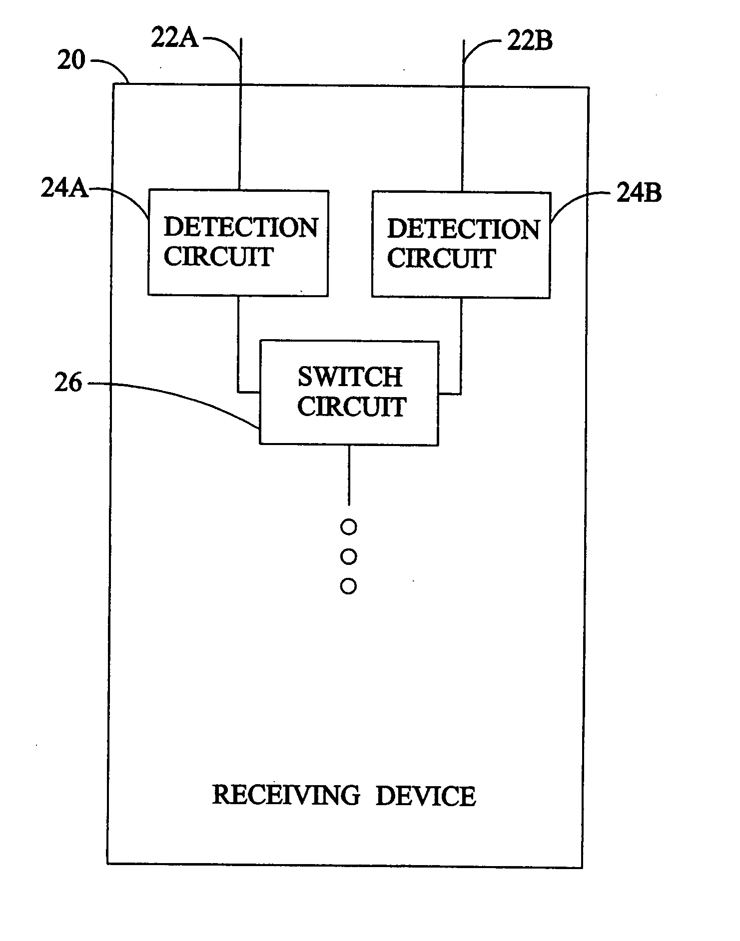
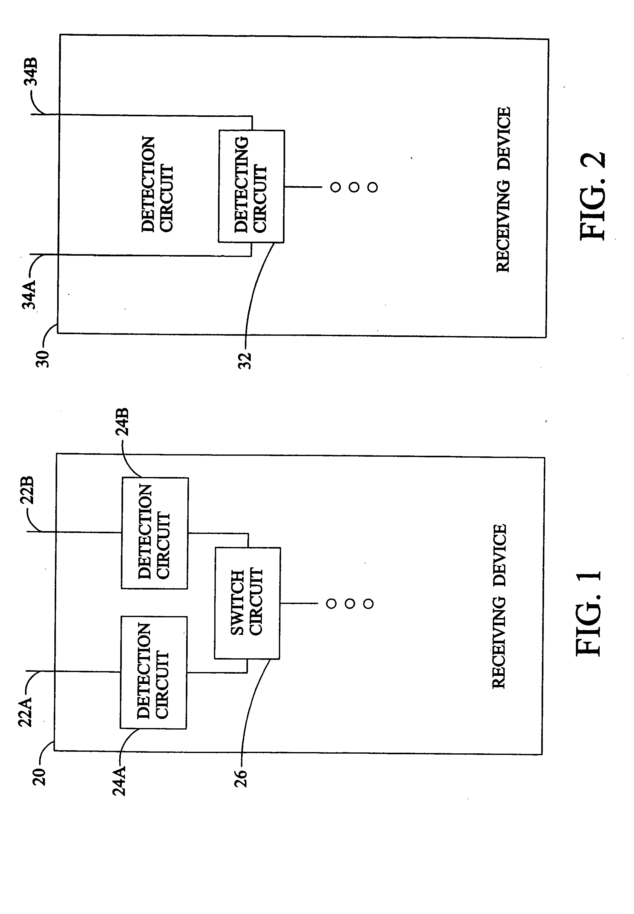
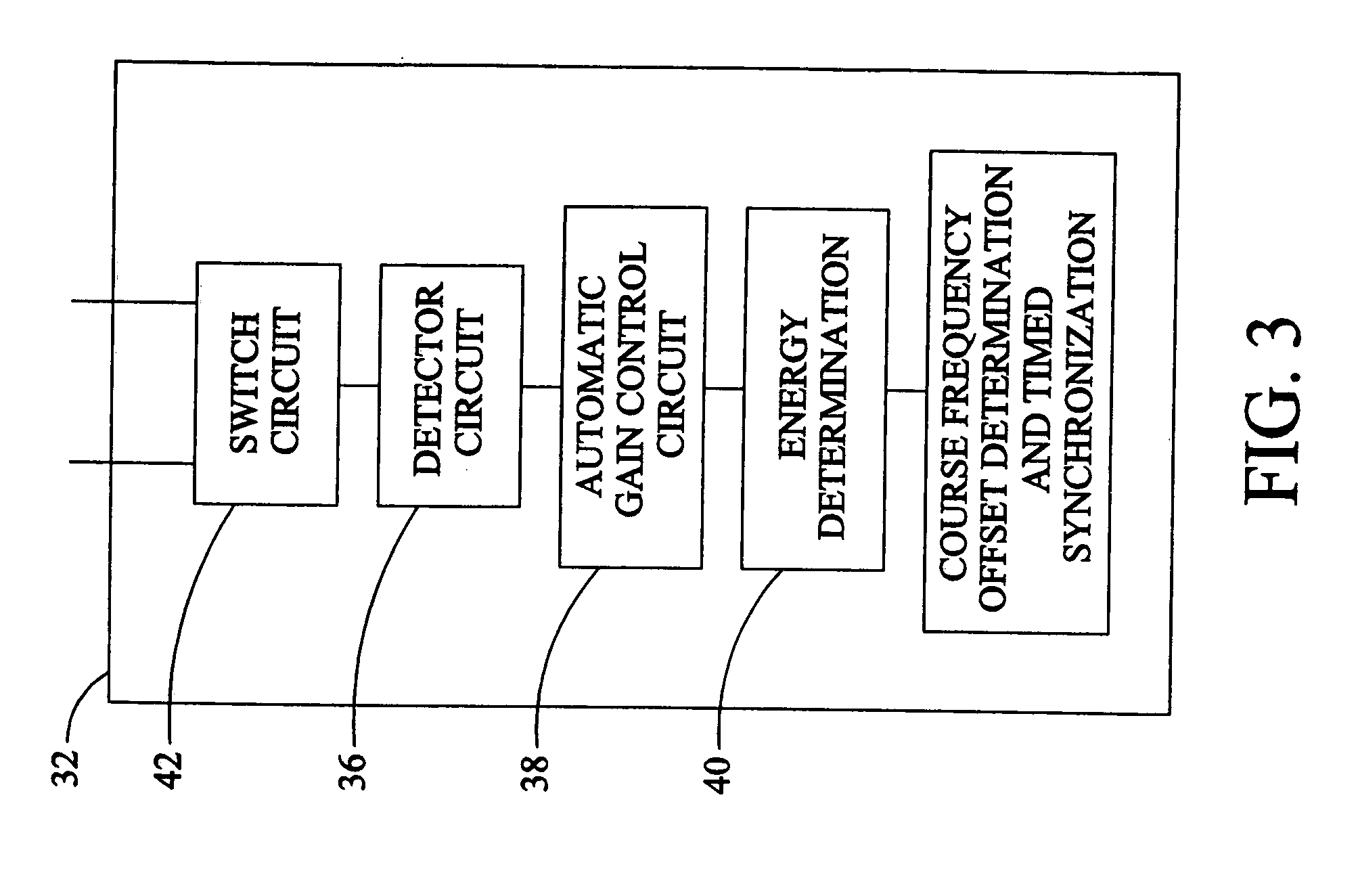
[0018] Referring to FIG. 2, a receiving device 30 includes one detecting circuit 32 switched between two or more spaced apart antennas 34a, 34b. In this manner the receiving device 30 only requires a single detecting circuit 32 thereby reducing power consumption and expense. The P802.11A standard requires the determination of many parameters with the ten short symbols provided during the short training sequence. Referring also to FIGS. 3 and 4, the first symbol is sensed by a detector circuit 36 of the detecting circuit 32 from one of the antennas 32a, 32b to sense a data unit. The second symbol sensed by the detector circuit 36 is used by the AGC circuit 38, as previously described. The AGC circuit 38 may require one or more symbols. The third and fourth symbols sensed by the detector circuit 36 are used by the energy determination circuit 40 to measure the signal strength. Next, a switch circuit 42 switches to the other antenna 32a, 32b during the fifth symbol. The sixth symbol is...


PUM


Abstract

A system adjusts a receiving device in response to sensing symbols. An automatic gain control is adjusted in response receiving a first symbol of a data unit from a first antenna. After adjusting the automatic gain control at least a second and a third symbol of the data unit are received, and in response thereto (1) a first energy of at least one of the second and third symbols is calculated, (2) a first frequency offset of at least one of the second and third symbols is calculated, and (3) a first temporal offset of at least one of the second and third symbols is calculated. The automatic gain control in response receiving a fourth symbol of the data unit from a second antenna is received. After adjusting the automatic gain control at least a fifth and a sixth symbol of the data unit is calculated, and in response thereto (1) a second energy of at least one of the fifth and sixth symbols is calculated, (2) a second frequency offset of at least one of the fifth and sixth symbols is calculated, and (3) a second temporal offset of at least one of the fifth and sixth symbols is calculated. At least one of the first and second antenna is selected based upon a comparison between the first and second energy. In this manner, antenna diversity selection may be performed within a limited duration of available symbols.

Description

[0001] This application claims priority of U.S. patent application Ser. No. 09 / 510,907; filed on Feb. 23, 2000; which claims the benefit of Provisional Patent Application Ser. No. 60 / 141,419; filed Jun. 29, 1999BACKGROUND OF THE INVENTION [0002] The present invention relates to a communication system including antenna selection diversity. [0003] The Institute of Electrical and Electronic Engineers (IEEE), DRAFT SUPPLEMENT TO STANDARD FOR INFORMATION TECHNOLOGY-TELECOMMUNICATIONS AND INFORMATION EXCHANGE BETWEEN SYSTEMS—LOCAL AND METROPOLITAN AREA NETWORKS—SPECIFIC REQUIREMENTS—PART 11: WIRELESS LAN MEDIUM ACCESS CONTROL (MAC) AND PHYSICAL LAYER (PHY) SPECIFICATIONS: HIGH SPEED PHYSICAL LAYER IN THE 5 GHz BAND, IEEE P802.11A / D7.0, July 1999, is part of a family of standards for wireless Local and Metropolitan Area Networks (hereinafter LAN). The proposed standard specifies certain characteristics of a high speed, digital, wireless communication LAN based on Orthogonal Frequency Divis...

Claims


Application Information

Patent Timeline
Patent Type & Authority Applications(United States)
IPC IPC(8): H04B7/08
CPCH04B7/0808
Inventor KANDALA, SRINIVAS
Owner SHARP KK
Why Eureka
Try Eureka