Downhill speed controller

a technology of speed control and control system, applied in brake systems, process and machine control, instruments, etc., can solve problems such as errors under gravity influence, system cost increase, and control system may be brought into a control disabled state, so as to improve controllability, improve stability, and improve controllability

Inactive Publication Date: 2005-05-05
NIHON KENKI CO LTD
View PDF8 Cites 80 Cited by
  • Summary
  • Abstract
  • Description
  • Claims
  • Application Information

AI Technical Summary

Benefits of technology

[0006] A first object of the present invention is to provide a downhill speed control system in which a target vehicle speed is set in advance, thereby improving not only controllability when a vehicle runs down a slope, but also operability in setting of the target vehicle speed by an operator.
[0007] A second object of the present invention is to provide a d

Problems solved by technology

This has raised a first problem that, if the actual vehicle speed at the time when the vehicle has entered the downward slope differs much from that set by the target vehicle speed setting circuit, the control system may be brought into a control disabled state.
Also, when trying to detect parameters required in control for braking a vehicle running down a slope, such as a slope condition, a load and a gradient, as proposed in JP-A-6-135260, the system cost is necessarily increased.
Further, a generally used inclinometer often causes errors under an influence o

Method used


Image

  • Downhill speed controller
  • Downhill speed controller
  • Downhill speed controller

Examples


first embodiment

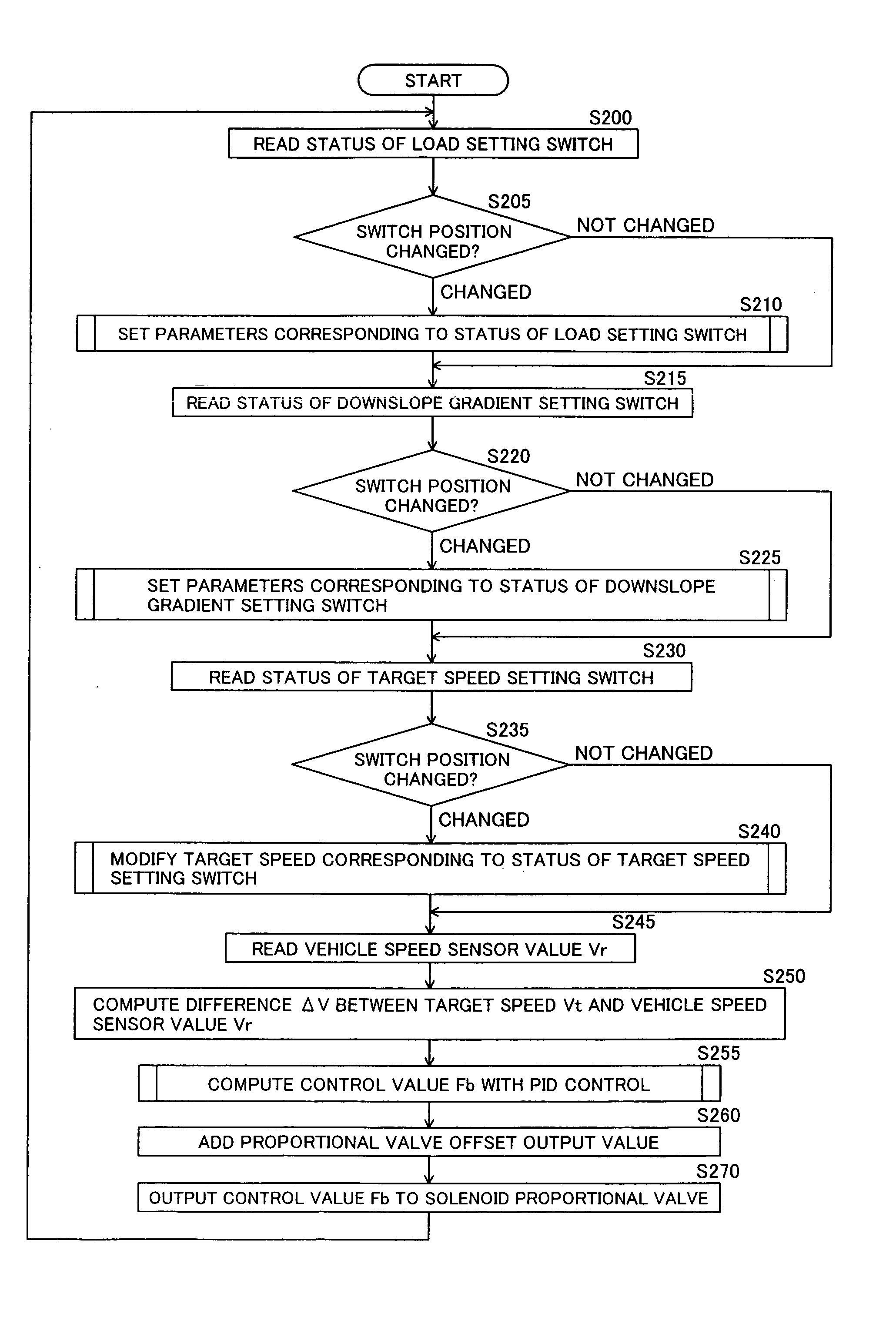
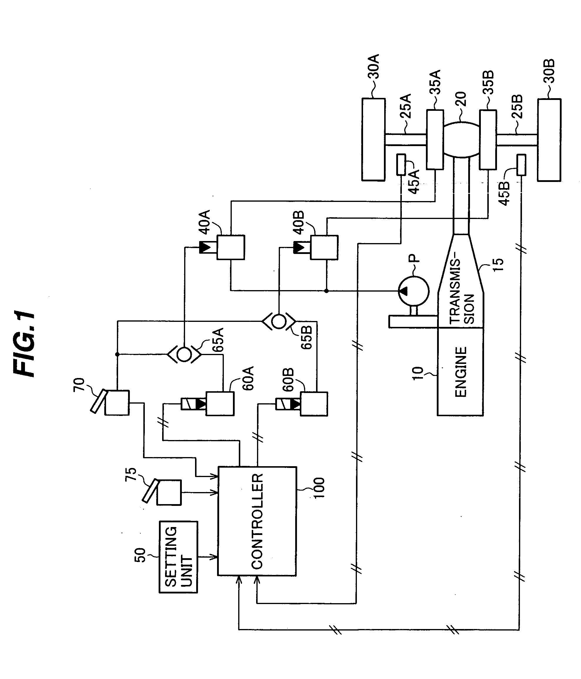
[0057] The configuration and operation of a downhill speed control system according to the present invention will be described below with reference to FIGS. 1 to 3. In this embodiment, the present invention is applied to a dump truck.

[0058]FIG. 1 is a block diagram showing the system configuration of the dump truck employing the downhill speed control system according to the first embodiment of the present invention.

[0059] A driving force produced by an engine 10 is transmitted to two drive wheels 30A, 30B through a transmission 15, a differential gear 20 and axles 25A, 25B, thereby running a body of the dump truck. Retarder brakes 35A, 35B for applying braking forces to the drive wheels 30A, 30B are attached respectively to the axles 25A, 25B. Hydraulic pressures are supplied to the retarder brakes 35A, 35B through brake valves 40A, 40B from a pump P driven by the engine 10.

[0060] Vehicle speed sensors 45A, 45B for detecting wheel rotation speeds are disposed respectively in asso...

second embodiment

[0079] The configuration and operation of a downhill speed control system according to the present invention will be described below with reference to FIGS. 1 and 4 to 7. In this embodiment, the present invention is applied to a dump truck.

[0080] The system configuration of the dump truck employing the downhill speed control system according to this embodiment is the same as that shown in FIG. 1.

[0081]FIG. 4 is a system block diagram showing the configuration of the downhill speed control system according to the second embodiment of the present invention.

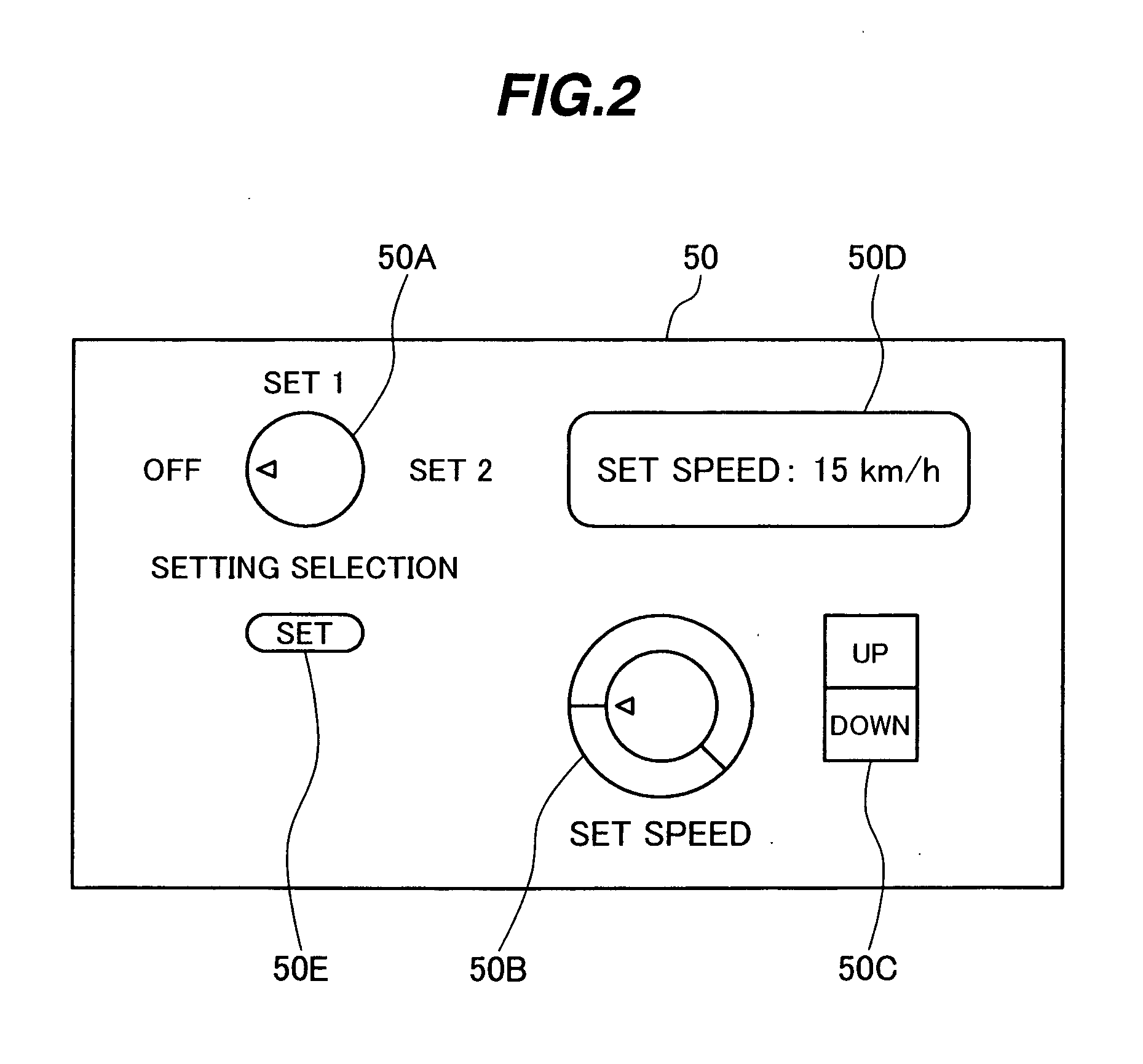
[0082] A setting unit 50 has a target speed setting switch 50XA, a downslope gradient angle setting switch 50XB, and a load setting switch 50XC. These setting switches 50XA, 50XB and 50XC are each in the form of a rotary switch or the like, which can set a setting value while changing it in a stepwise way. The target speed setting switch 50XA is a switch operated by the operator for changeably setting the speed running down a slop...

third embodiment

[0104] The configuration and operation of a downhill speed control system according to the present invention will be described below with reference to FIGS. 1, 8 and 9. In this embodiment, the present invention is applied to a dump truck.

[0105] The system configuration of the dump truck employing the downhill speed control system according to this embodiment is the same as that shown in FIG. 1.

[0106]FIG. 8 is a system block diagram showing the configuration of the downhill speed control system according to this embodiment.

[0107] A setting unit 50 has a target speed setting switch 50YA. The setting switch 50YA is in the form of a rotary switch or the like, which can set a setting value while changing it in a stepwise way. The target speed setting switch 50YA is a switch operated by the operator for changeably setting the speed running down a slope. The setting switch 50YA is able to select and set one of three target speeds, for example, 10 km / h, 12 km / h and 15 km / h.

[0108] A contr...


PUM


Abstract

The invention is intended to provide a downhill speed control system which employs a method of setting a target vehicle speed in advance, thereby improving controllability when a vehicle runs down a slope, and giving an operator improved operability in setting of the target vehicle speed. Brakes are controlled so that, when the vehicle runs down the slope, an actual vehicle speed is matched with a target speed set by a switch which can set the target speed by selectively or continuously changing plural preset speeds. Also, control constants for PID control are modified depending on settings of a downslope gradient setting switch and a load setting switch. When an acceleration computed from the actual vehicle speed is larger than a target acceleration, the strength of applied brake is increased.

Description

TECHNICAL FIELD [0001] The present invention relates to a downhill speed control system for controlling a speed of a vehicle running down a slope, and more particularly to a downhill speed control system suitable for automatically controlling a downhill speed by properly applying the brake when a vehicle having a large loading capacity, such as a dump truck, runs down a slope. BACKGROUND ART [0002] A method of adjusting the strength of applied brake with an operator operating a foot brake or a brake lever has hitherto been practiced for the purpose of keeping a vehicle speed at a control target value when a vehicle runs down a slope. In mines or the likes where a downward slope continues over a long distance, however, it is troublesome for the operator to operate the brake whenever an occasion requires. In a downhill speed control system for releasing the operator from the troublesome braking operation in such a case, as disclosed in, e.g., JP-A-6-135260, a target vehicle speed is s...

Claims


Application Information

Patent Timeline
IPC IPC(8): B60K31/04B60T7/12B60T8/24
CPCB60K31/04B60T7/12B60T7/122B60T8/245Y10T477/80B60W2540/10B60W2540/12B60W2550/142Y10T477/816B60T2201/04B60W2552/15B60W2050/0011
Inventor WATANABE, YUTAKAWATANABE, HIROSHITOKUDA, YASUSHI
Owner NIHON KENKI CO LTD
Why Eureka
Try Eureka