Two-cycle engine for counter-rotation especially for aviation applications

a technology of two-cycle engines and aviation applications, applied in the direction of liquid fuel engines, vessel construction, marine propulsion, etc., can solve the problems of inherently unsuitable engines, affecting the practical implementation of the engine, and difficulty in accessing, so as to improve thrust performance, eliminate the transfer of torque to the aircraft, and inherently balanced output torque

Inactive Publication Date: 2005-05-12
SCHWAM PAUL A
View PDF21 Cites 8 Cited by
  • Summary
  • Abstract
  • Description
  • Claims
  • Application Information

AI Technical Summary

Benefits of technology

[0033] Therefore, according to these and other objectives, one aspect of this invention consists of a counter-rotating 2 cycle-piston engine having an output shaft rotatably mounted to the frame of an aircraft. The engine block, is suitably journaled on the shaft to permit its counter-rotation. Internal combustion power is transmitted to the output shaft by means of one or more pistons slidably received within cooperating combustion chamber cylinders cooperatively connected to the crankshaft which translates expanding gas to rotational motion in the conventional manner, and according to the invention, produces concurrent rotation of the shaft and counter-rotation of the engine block. Dual propellers mounted on the shaft and on the block provide improved thrust performance, inherently balanced output torque and moments of inertia between the two counter-rotating masses, and virtually eliminate the transfer of torque to the aircraft. Also, according to the invention, the interior surfaces of the crankcase have been modified and a poston port added to facilitate the regular transfer of all engine fluids to the combustion chamber, and to eliminate the internal buildup of fluids which inhibit engine function during operation.

Problems solved by technology

All of the various solutions disclosed in these patents involve complicated engine mounting, inlet / exhaust porting and lubricating systems that have greatly affected their practical implementation.
The mechanical configuration of 4 cycle reciprocating-piston engines, which comport the use of pistons traveling radially with respect to the axis of rotation of the crankshaft, and include one or more reservoir of oil for lubrication, produce an inherently unsuitable engine.
Each piston operates radially from a corresponding crank in the output shaft, access to the combustion chamber for fuel delivery is necessarily limited to the distal end of each cylinder, which creates access difficulties during rotation of the cylinders and intake flow difficulties since flow to the combustion chamber is necessarily against centrifical force.
Lubrication is similarly complicated by centrifical-force effects that cause crankcase oil, necessary for lubrication, usually pooled in a reservoir below the crankshaft and away from the pistons, to accumulate in various locations, away from the crankshaft, including behind the pistons.
Centrifical force acting upon accumulations of oil at this location causes severe engine imbalances, and also directly opposes the desires action created from internal combustion.
Accordingly, no counter-rotating engine has been successfully implemented commercially using 4 cycle reciprocating-piston configurations in spite of the theoretical advantages provided by this concept.
Reservoirs of oil under the influence of centrifical force adversely affects the balance of the crankcase and inhibits the reciprocating motion of the pistons.
It has been noted the engine functions progressively less normally at higher block RPMs likely due to adverse reaction to increasing centrifical forces acting upon the fuel / oil mixture.
No fully accessorized, full functioning, full scale counter-rotating engine has been successfully implemented commercially using 2 cycle reciprocating-piston configurations in spite of the theoretical application to aviation provided by this concept.

Method used


Image

  • Two-cycle engine for counter-rotation especially for aviation applications
  • Two-cycle engine for counter-rotation especially for aviation applications
  • Two-cycle engine for counter-rotation especially for aviation applications

Examples


Embodiment Construction

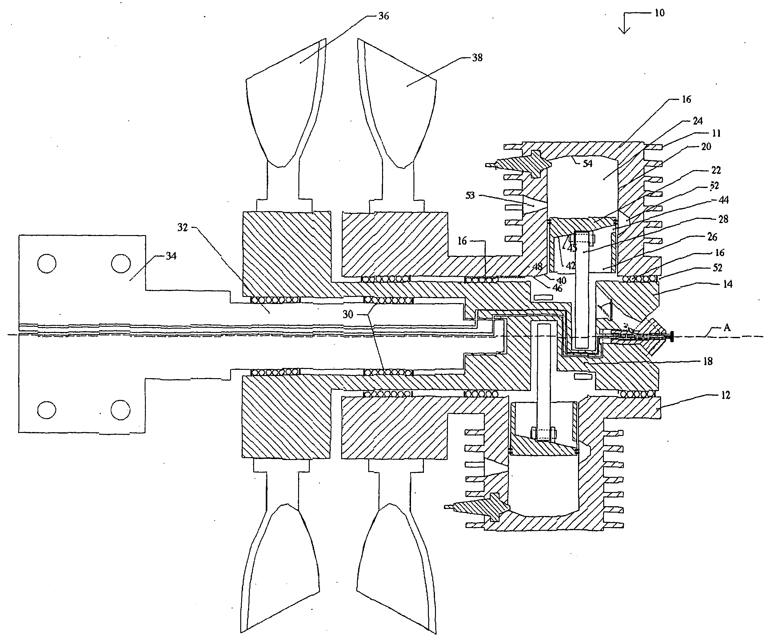
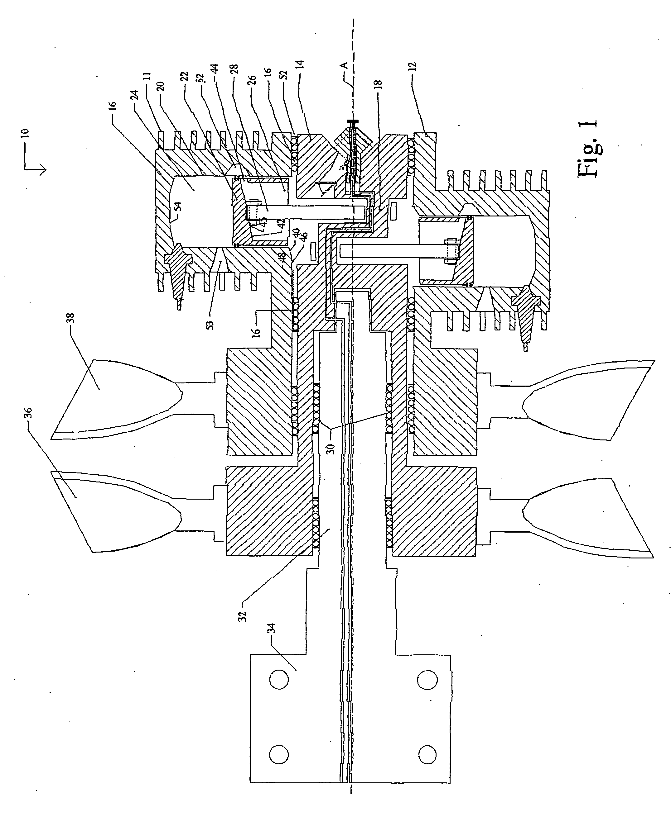
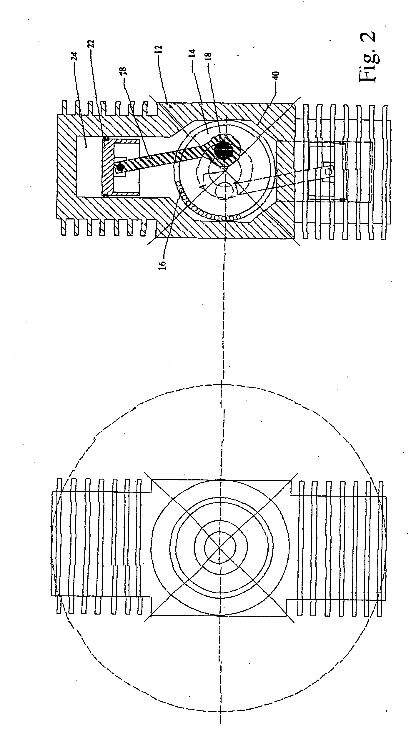
[0043] This invention lies in the recognition that a two cycle engine with an output shaft can be modified to facilitate the counter-rotation of the engine's combustion chamber about the same axis as the output shaft with propellers advantageously mounted on both the engine's output shaft and housing, respectively.

[0044] The primary aspect of this invention resides in the recognition that 2 cycle engines, absent of a constant reservoir of crankcase oil, provide an opportunity to counter rotate the crankcase and combustion chambers without the negative effects of uncontrolled crankcase oil under centrifical force.

[0045] Careful control of transient fluids inside the crankcase, under centrifical force, can enhance the fuel / oil flow performance. In the present invention, all internal surfaces of the counter-rotating crankcase facing the axis of rotation are angled away from the central axis to promote the unrestricted flow of accumulated oil radially away from the output shaft axis a...


PUM


Abstract

A counter-rotating 2 cycle piston engine with a combustion chamber and an output shaft rotatably mounted to rotate independently about the same propeller centerline of an aircraft. the Internal combustion power is transmitted to the output shaft by means of a conventional piston, rod, crankshaft configuration journaled to the combustion chamber or engine block in the traditional manner thereby producing concurrent rotation of the shaft and counter-rotation of the engine block. Interior surfaces of the combustion chamber and pistons are angled to control the oil flow inside the crankcase and eliminate unwanted ponding. The pistons are modified to transfer fluid accumulations to the combustion chamber. A throttle is located at the axis of rotation to function normally without the effects of centrifical force. Dual propellers mounted on the shaft and on the block improve thrust performance, balance the torques and moments of inertia of the two counter-rotating masses, All rotational output torque automatically balances itself between counter rotating propellers and is converted into propulsion. No rotational torque is allowed to be transmitted to the airframe through the counter-rotating engine mount.

Description

RELATED APPLICATIONS [0001] This application is based on U.S. Provisional Application No. 60 / 520,134, filed Nov. 15, 2003, and is a continuation-in-part of U.S. application Ser. No. 10 / 417,364, filed on Apr. 16, 2003, which is based on U.S. Provisional Application No. 60 / 381,625, filed on May 17, 2002.BACKGROUND OF THE INVENTION [0002] 1. Field of the Invention [0003] This invention is related in general to the field of counter-rotating engines and, in particular, to a novel configuration for a 2 cycle engine with a novel mounting system, and one or more sets of simultaneously firing cylinders, that enables the advantageous counter-rotation of the engine's shaft and block for suitable applications. [0004] 2. Description of the Related Art [0005] All internal combustion engines share the characteristic of transforming the pressure generated by the combustion of a fuel into the useful rotation of a shaft. Piston engines cause the rotation of the shaft by expanding the combustion gases...

Claims


Application Information

Patent Timeline
Patent Type & Authority Applications(United States)
IPC IPC(8): B64D27/02B64D35/06F01C1/22F02B53/00F04C2/10F04C11/00F04C29/00
CPCB64D27/02B64D35/06F01C1/22F02B53/00Y02T10/17F04C2/10F04C11/006F04C29/0021F04C2240/603F02B2053/005Y02T10/12
Inventor SCHWAM, PAUL A.
Owner SCHWAM PAUL A
Why Eureka
Try Eureka