
Torsion beam axle suspension

a technology of torsion beam and axle, which is applied in the direction of suspension, coupling, transportation and packaging, etc., can solve the problems of omitting torsion beam axle suspension, and achieve the effects of enhancing productivity, reducing weight and production expenses, and reducing friction

Inactive Publication Date: 2005-05-12
HYUNDAI MOBIS CO LTD
View PDF30 Cites 25 Cited by
  • Summary
  • Abstract
  • Description
  • Claims
  • Application Information

AI Technical Summary

Benefits of technology

[0010] To solve the above-indicated problems, it is, therefore, an object of the present invention to provide a torsion beam axle suspension capable of reducing the weight and production expenses as well as enhancing productivity.
[0011] It is another of the present invention to provide a torsion beam axle suspension capable of considerably decreasing a friction caused by movement of the shock absorber even though the transverse force is applied, thus enhancing the riding comfort.
[0012] It is yet another object of the present invention to provide a torsion beam axle suspension capable of easily adjusting a position of the shock absorber without exchange of parts, thus improving productivity and assembling capability, as well as obtaining easy management and cost saving by sharing of the parts.

Problems solved by technology

However, the foregoing torsion beam axle suspension has the following problem.

Method used


Image

  • Torsion beam axle suspension
  • Torsion beam axle suspension
  • Torsion beam axle suspension

Examples


Embodiment Construction

[0023] A preferred embodiment of the present invention will now be described with reference to the accompanying drawings. In the following description, same drawing reference numerals are used for the same elements even in different drawings. The matters defined in the description such as a detailed construction are nothing but the ones provided to assist in a comprehensive understanding of the invention. Thus, it is apparent that the present invention can be carried out without those defined matters. Also, well-known functions or constructions are not described in detail since they would obscure the invention in unnecessary detail.

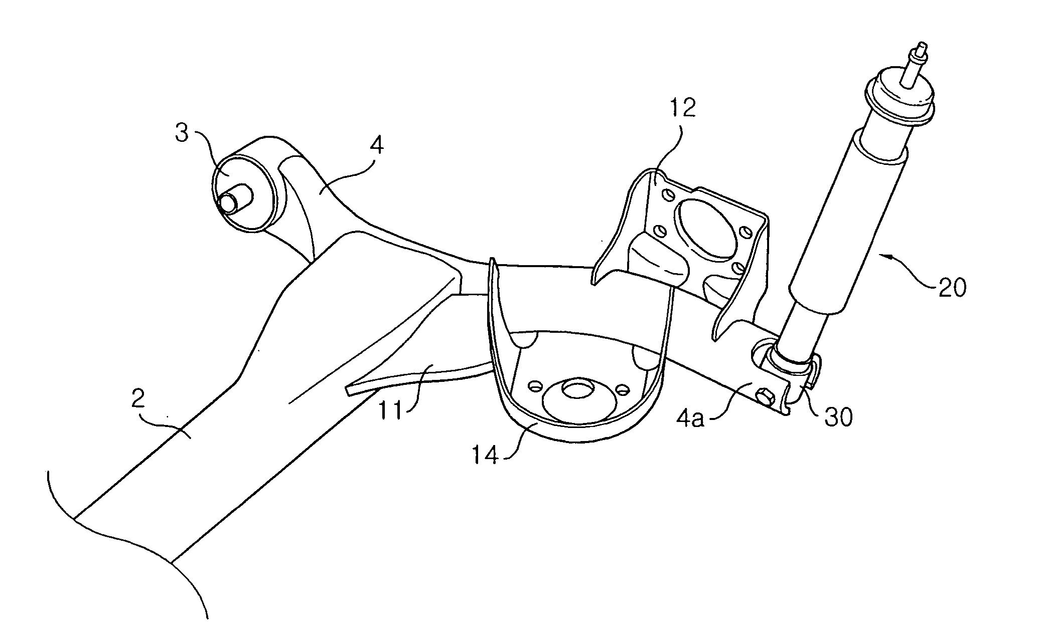
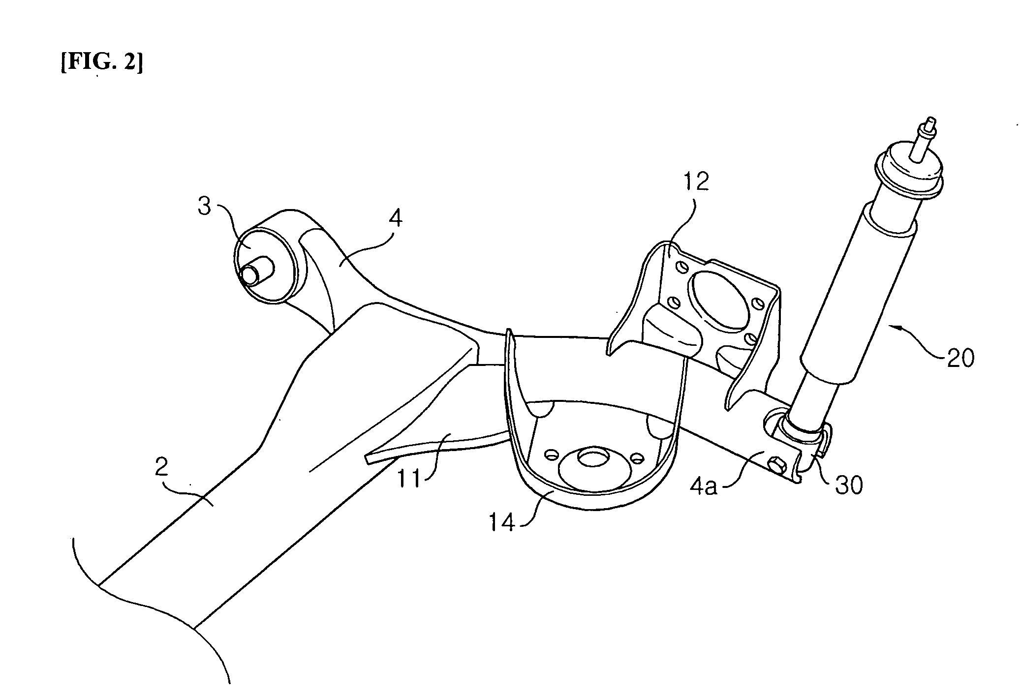
[0024]FIG. 2 is a perspective view illustrating a torsion beam axle suspension according to a preferred embodiment of the present invention, FIG. 3 is an exploded perspective view illustrating the shock absorber and the mount of FIG. 2, and FIG. 4 is an assembly cross-sectional view of FIG. 2.

[0025] As shown in FIG. 2, a torsion beam axle suspension of ...


PUM


Abstract

A torsion beam axle suspension is provided, in which a shock absorber is directly mounted on right and left trailing arms and is further mounted to the mount by a ball joint. Thus, it is possible to reduce the weight and production expenses, thus to enhance productivity. Further, it is possible to considerably decrease a friction caused by movement of the shock absorber even though the transverse force is applied, thus to enhance the riding comfort.

Description

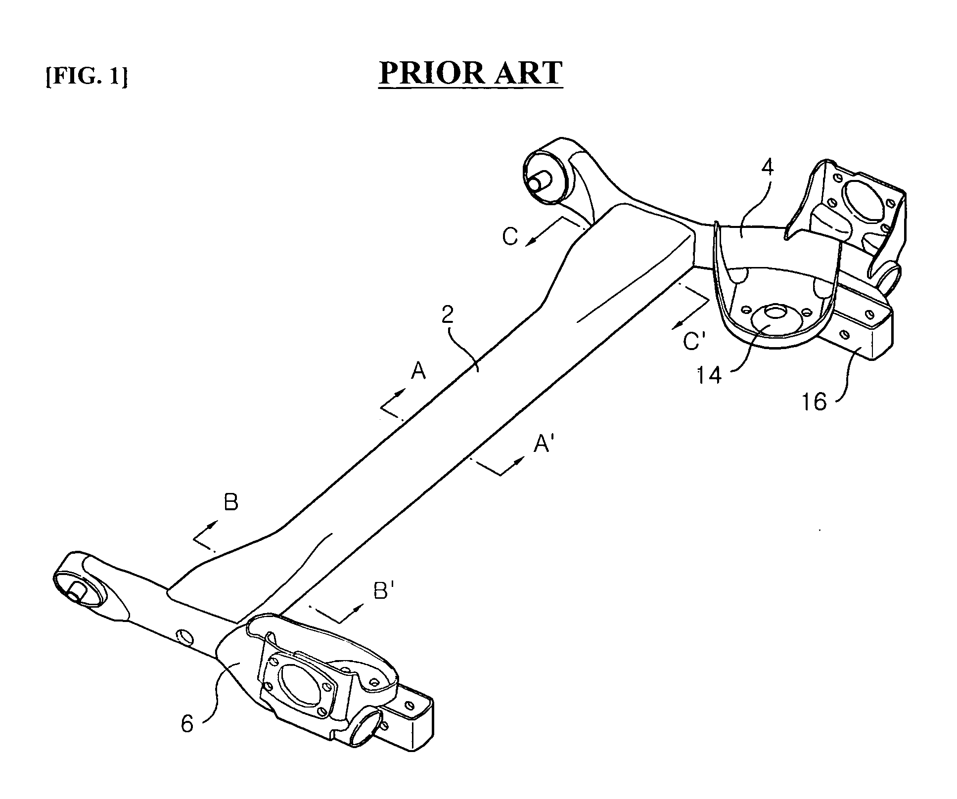
RELATED APPLICATIONS [0001] The present disclosure relates to subject matter contained in priority Korean Application No. 10-2003-0079344, filed on Nov. 11, 2003, which is herein expressly incorporated by reference in its entirety. BACKGROUND OF THE INVENTION [0002] 1. Field of the Invention [0003] The present invention relates to a torsion beam axle suspension, and more particularly to a torsion beam axle suspension in which a shock absorber is directly mounted on right and left trailing arms and is further mounted to the mount by a ball joint. [0004] 2. Description of the Related Art [0005] In general, a suspension is the apparatus, which is provided between a body and a wheel, for preventing vibration or shock transmitted from a road surface during traveling from being directly transmitted to a body, thus preventing a damage of the body as well as securing riding comfort and stability. In the vehicle, a torsion beam axle suspension used for a suspension for rear wheels includes a...

Claims


Application Information

Patent Timeline
IPC IPC(8): B60G11/18B60B35/04B60G13/00B60G21/05
CPCB60B35/04B60G7/005B60G13/005B60G21/051B60G2204/1244B60G2204/129B60G2204/416B60G2206/10Y10T403/32311Y10T403/32795B60G11/18
Inventor CHOI, MIN-SEOK
Owner HYUNDAI MOBIS CO LTD
Learn More