Method and circuitry for implementing a differentially tuned varactor-inductor oscillator

a varactorinductor and differential tuning technology, applied in the direction of oscillator, pulse technique, pulse generator, etc., can solve the problems of single-ended signals, adverse effects of input control signals on the performance of pll, and more susceptible to noise interferen

Inactive Publication Date: 2005-05-12
AVAGO TECH WIRELESS IP SINGAPORE PTE
View PDF10 Cites 4 Cited by
  • Summary
  • Abstract
  • Description
  • Claims
  • Application Information

AI Technical Summary

Benefits of technology

[0007] In one exemplary embodiment, the present invention includes an LC tank circuit having a couple of terminals, a first and second capacitors, and a first and second varactors. The first and second varactors are connected in series forming a first and a second node. The first capacitor connects the first node and one terminal of the LC tank circuit. The second capacitor connects the second node and the other terminal of the LC tank circuit. A pair of differential input control signals is applied across the first and the second varactors to tune the LC tank circuit thereby generating an oscillator output.
[0008] Accordingly, in one embodiment, the present invention provides a voltage-controlled oscillator including: an LC tank circuit, a plurality of varactors each having a first and a second terminal; and a plurality of capacitors respectively coupling said LC tank circuit to said plurality of varactors; wherein, a pair of differential input control signals are applied across said first and second terminals of each of said plurality of varactors to tune said LC tank circuit so as to generate an oscillator output.
[0009] Accordingly, in another embodiment, the present invention provides a method for implementing a voltage-controlled oscillator including: connecting a first varactor and a second varactor in series thereby forming a first and a second node; coupling a first capacitor between an LC tank circuit and said first node; coupling a second capacitor between said LC tank circuit and said second node; and applying a pair of differential input control signals across said first varactor and said second varactor respectively.

Problems solved by technology

Since the VCO is the part of the PLL which produces an ac output signal whose frequency is proportional to the input control signal, external unwanted noise affecting the input control signal has an adverse impact on the performance of the PLL.
Due to their single-ended nature, single-ended signals, however, are more susceptible to noise interference.

Method used


Image

  • Method and circuitry for implementing a differentially tuned varactor-inductor oscillator
  • Method and circuitry for implementing a differentially tuned varactor-inductor oscillator
  • Method and circuitry for implementing a differentially tuned varactor-inductor oscillator

Examples


Embodiment Construction

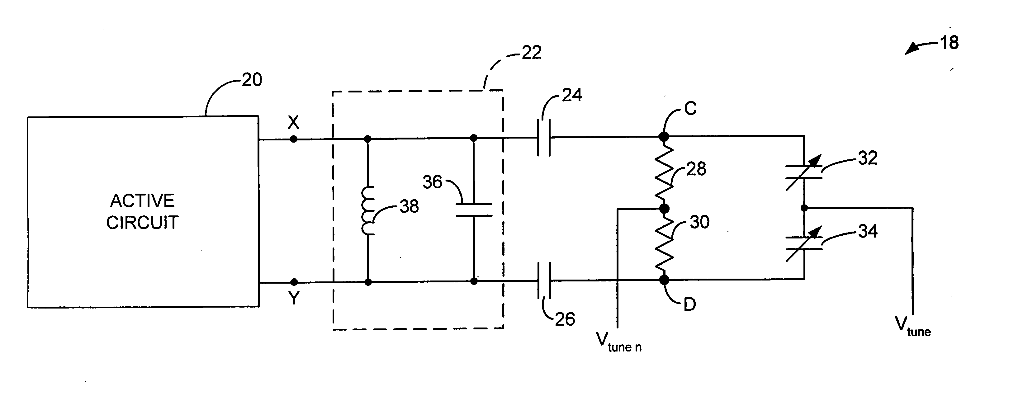
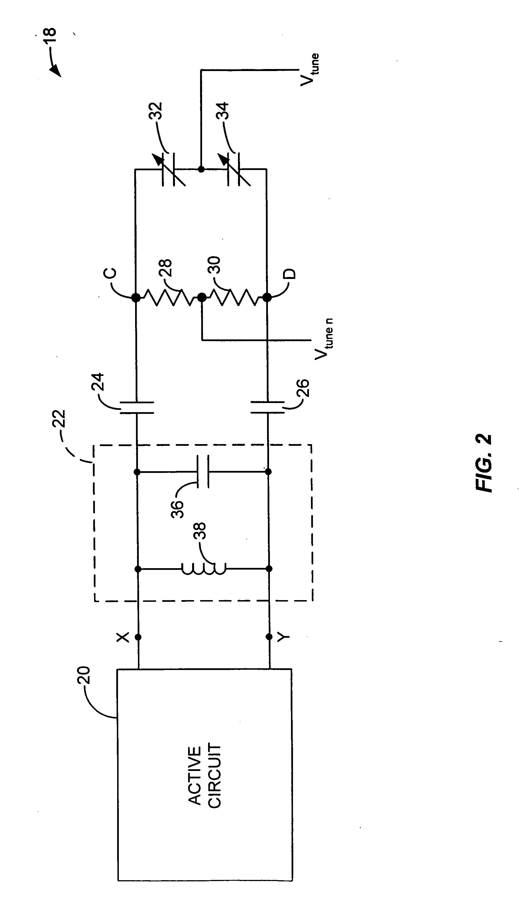
[0014] The present invention will now be described. FIG. 2 shows a simplified circuit diagram of an exemplary embodiment of the present invention. As shown in FIG. 2, the exemplary embodiment shows a VCO 18 having an active circuit 20 having a couple of terminals X,Y, an LC tank circuit 22, a first capacitor 24, a second capacitor 26, a first resistor 28, a second resistor 30, a first varactor 32 and a second varactor 34. Further, the LC tank circuit 22 includes an inductor 38 and a third capacitor 26. These various elements are connected as follows.

[0015] The LC tank circuit 22 is connected across the terminals X and Y of the active circuit 20. The two resistors 28 and 30 are connected in series. The two varactors 32 and 34 are, similarly, connected in series. The two resistors 28 and 30 in series and the two varactors 32 and 34 in series are then connected in a parallel manner forming a first node C and a second node D. The first capacitor 24 is then used as a bridge connecting t...


PUM


Abstract

The present invention generally relates to voltage-controlled oscillators. More specifically, the present invention relates to method and circuitry for implementing a differentially tuned varactor-inductor oscillator. In one exemplary embodiment, the present invention includes an LC tank circuit having a couple of terminals, a first and second capacitors, and a first and second varactors. The first and second varactors are connected in series forming a first and a second node. The first capacitor connects the first node and one terminal of the LC tank circuit. The second capacitor connects the second node and the other terminal of the LC tank circuit. A pair of differential input control signals is applied across the first and the second varactors, respectively, to tune the LC tank circuit thereby generating an oscillator output.

Description

CROSS-REFERENCES TO RELATED APPLICATIONS [0001] The present application claims the benefit of priority under 35 U.S.C. § 119 from the provisional patent application, U.S. Patent Application Ser. No. 60 / 184,721, filed on Feb. 24, 2000, which is hereby incorporated by reference as if set forth in full in this document.BACKGROUND OF THE INVENTION [0002] The convergence of various high speed data communication technologies (e.g., Ethernet, fiber channel, IEEE firewire links) into the gigabit domain has focused the efforts of integrated circuit designers on developing high speed circuit techniques for processing broadband signals. A circuit block that is commonly found in these types of communication applications is a voltage-controlled oscillator (VCO). As the main building block of phase-locked loops (PLLs), the VCO can be found, for example, in clock and data recovery circuits. [0003] The VCO is typically an important element in determining the overall noise performance of a PLL. Sinc...

Claims


Application Information

Patent Timeline
Patent Type & Authority Applications(United States)
IPC IPC(8): H03B5/00H03B5/12
CPCH03B5/1228H03B5/1256H03B5/1253H03B5/1212
Inventor GUTIERREZ, GERMAN
Owner AVAGO TECH WIRELESS IP SINGAPORE PTE
Why Eureka
Try Eureka