Balanced output circuit and electronic apparatus utilising the same

a balanced output circuit and output circuit technology, applied in the direction of negative-feedback circuit arrangement, amplifier with semiconductor devices/discharge tubes, amplifier combinations, etc., can solve the problem of increasing the manufacturing cost of an ic that incorporates the btl amplifier, and achieve the effect of reducing the cost of an ic (lsi) incorporating the balanced output circuit and reducing the capacitor

Inactive Publication Date: 2007-11-08
ROHM CO LTD
View PDF7 Cites 1 Cited by
  • Summary
  • Abstract
  • Description
  • Claims
  • Application Information

AI Technical Summary

Benefits of technology

[0020] The invention can generate balanced outputs by controlling the comparison voltage of an inverting amplification circuit using a control amplification circuit so as to annihilate the DC offset voltage that exists between the inverted and non-inverted output signals of the inverting amplification circuit.
[0021] It should be noted that the comparison voltage is determined by the charging voltage of the equ...

Problems solved by technology

As a consequence, although the output circuit can control the DC offset voltage, the circuit has a complex struct...

Method used


Image

  • Balanced output circuit and electronic apparatus utilising the same
  • Balanced output circuit and electronic apparatus utilising the same
  • Balanced output circuit and electronic apparatus utilising the same

Examples


first embodiment

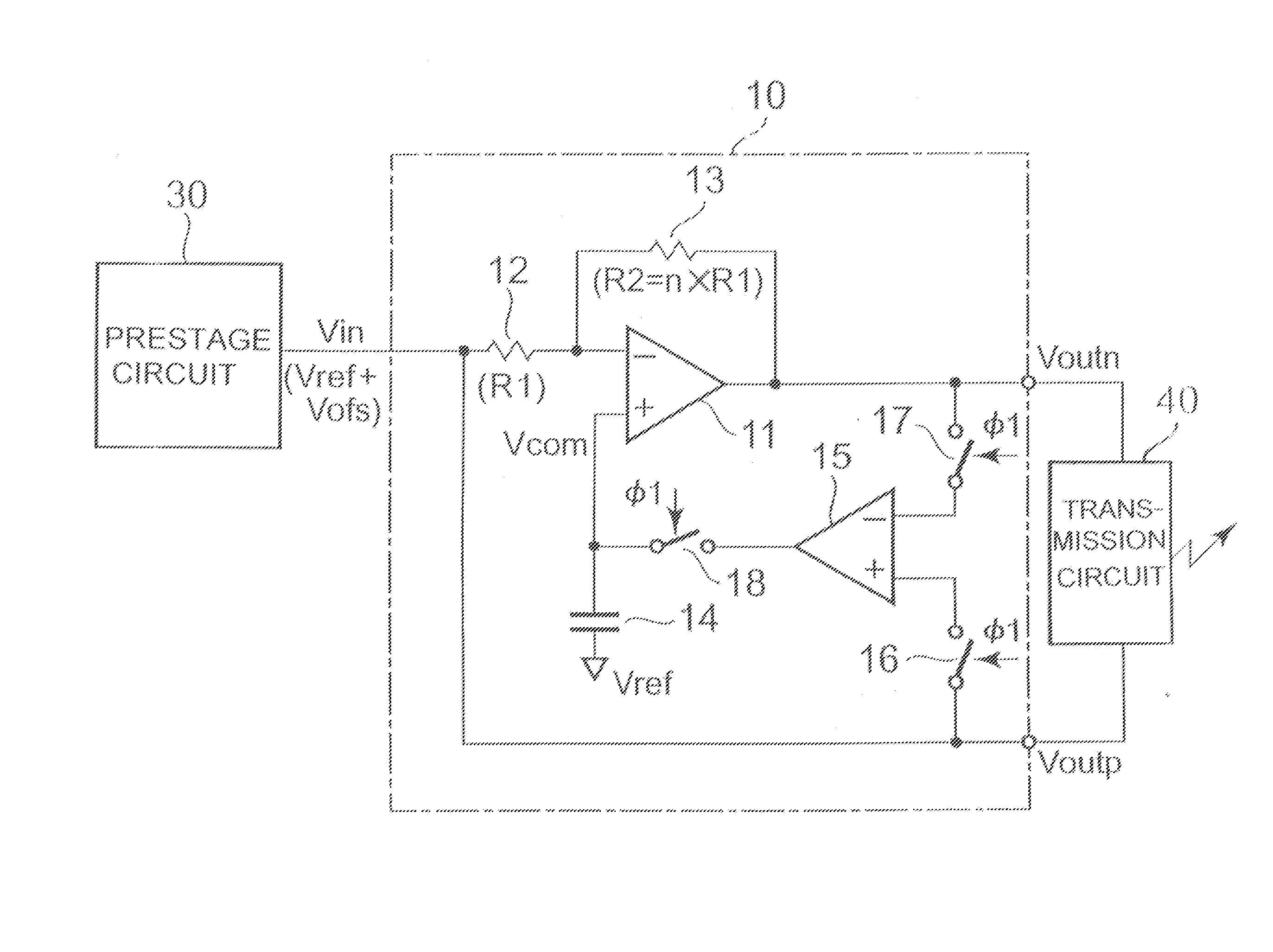
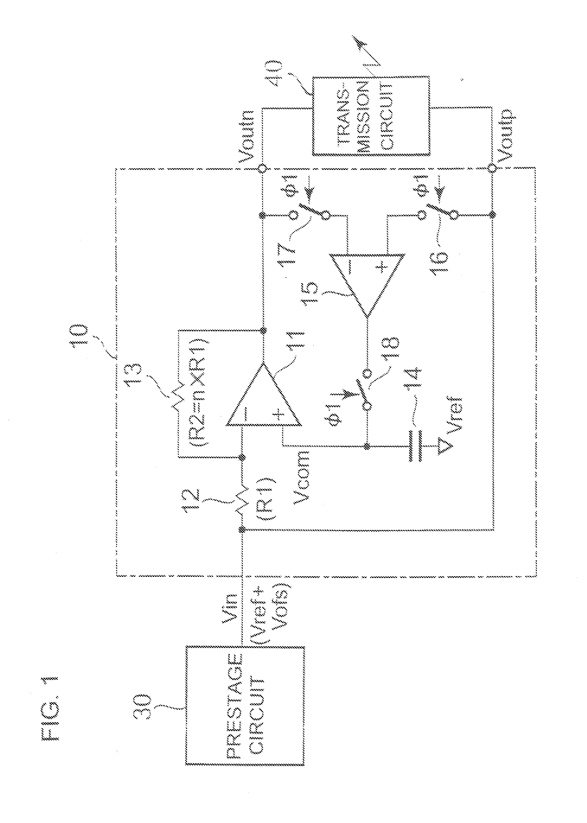
[0029] Referring to FIG. 1, there is shown an arrangement of a balanced output circuit 10 in accordance with the invention and an electronic apparatus such as a portable telephone utilizing the balanced output circuit. The balanced output circuit can be used in a balanced output part of an electric / electronic apparatus, such as a base-band signal transmitter of a portable telephone and a BTL speaker driver, adapted to output an inverted output signal in balance with a non-inverted output signal.

[0030] A prestage circuit 30 shown in FIG. 1 is adapted to process an AC audio signal, and outputs the AC (audio) signal superposed on a DC reference voltage Vref. It is often the case that the reference voltage Vref is superposed with a DC offset voltage Vofs resulting from variations in the characteristic properties of various circuit elements of the prestage circuit. That is, the output of the prestage circuit has a DC voltage, which amounts to the reference voltage Vref superposed with th...

second embodiment

[0051] Referring to FIG. 3, there is shown an arrangement of a balanced output circuit 10A in accordance with the invention. In the example shown in FIG. 3, a switch 19 for discharging the capacitor 14 is connected in parallel to the capacitor 14 (the switch referred to as discharging switch). The discharging switch 19 is a MOS transistor that can be turned on and off by a discharge signal 2.

[0052] It should be noted that the charged capacitor 14 undergoes natural discharge to loose its electricity. In the meanwhile, therefore, the capacitor may cause an error in the offset annihilation operation.

[0053] In order to prevent such condition from occurring, it is preferable to repeat offset annihilation operation periodically with a certain period of time or within a predetermined time. To do so, the switch 19 may be turned on by a discharge signal 2 only for a short time to temporally discharge the capacitor 14 prior to a further offset annihilation operation, in the manner as describ...


PUM


Abstract

In a balanced output circuit, an input signal inputted thereto is provided as a first output signal thereof on one hand, and on the other hand the input signal is inputted to an inverting amplification circuit and is compared with a comparison voltage before the signal is outputted as a second output signal. Based on the comparison of the first and second output signals, the comparison voltage is controlled by a charging voltage of a capacitor such that the DC voltage of the second output signal is equalized to that of the first output signal. Thus, the DC offset voltage between the first output signal (non-inverted output signal) and the second output signal (inverted output signal) can be properly annihilated by a simple circuit.

Description

TECHNICAL FIELD [0001] This invention relates to balanced output circuit for outputting balanced inverted and non-inverted outputs, and to an electronic apparatus, such as a portable telephone, utilizing such balanced output circuit. RELATED ART [0002] In a baseband signal transmission output part and a BTL (Balanced Transformer-less) speaker driver of a portable telephone for example, a balanced output circuit is used which is adapted to provide a non-inverted output that is in phase with an input signal and an inverted output that is out of phase by 180 degrees with the input signal. [0003] In a conventional electric power amplification circuit for use with audio equipment, an audio signal transmitted from a prestage circuit via a capacitor and an inverted feedback signal are inputted to a BTL amplifier. The BTL amplifier provides at the two BTL output terminals thereof an amplified audio signal and an amplified differential signal that is obtained by adding a reference voltage to...

Claims


Application Information

Patent Timeline
IPC IPC(8): H03F3/04
CPCH03F3/45932H03F2200/421H03F2203/45212H03F2203/45146H03F2203/45138H03F3/68H03F3/34
Inventor CHIDA, TAISUKE
Owner ROHM CO LTD
Why Eureka
Try Eureka