

Power conversion device
a technology of power conversion device and capacitor, which is applied in the direction of power conversion system, dc-dc conversion, electrical apparatus, etc., can solve the problems of increasing the size of the capacitor and the device, and achieve the effect of reducing the capacitance of the capacitor and reducing the siz
- Summary
- Abstract
- Description
- Claims
- Application Information
AI Technical Summary
Benefits of technology
Problems solved by technology
Method used
Image

Examples
embodiment 1
[0034]
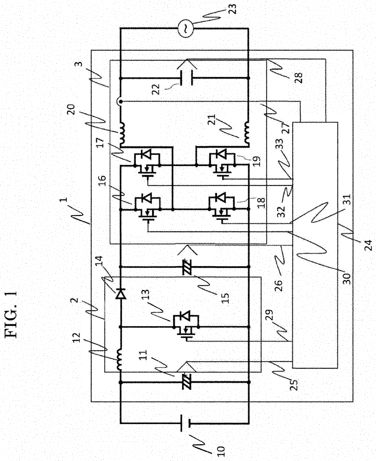
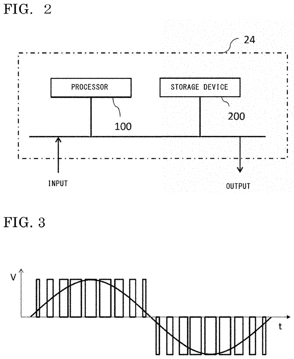
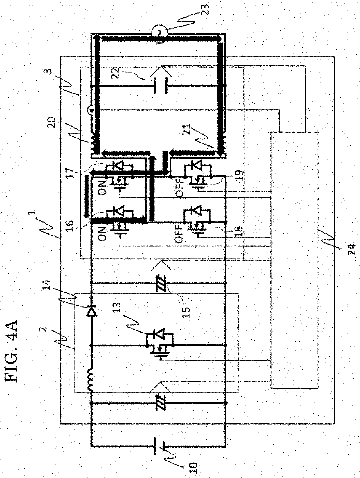
[0035]FIG. 1 shows the circuit configuration of a power conversion device 1 according to embodiment 1. The power conversion device 1 is composed of a converter 2, an inverter 3, and a control device 24, a DC power supply 10 is connected at the input of the converter 2, and a grid 23 is connected at the output of the inverter 3.
[0036]The converter 2 is composed of a reactor 12, a semiconductor switching element 13, and a diode 14. The reactor 12 has two terminals, the semiconductor switching element 13 has three terminals of a positive electrode, a negative electrode, and a control electrode, and the diode 14 has two terminals of an anode and a cathode.
[0037]One end of the reactor 12 is connected to the positive electrode of the semiconductor switching element 13 and the anode of the diode 14, and another end of the reactor 12 is connected to the positive side of the DC power supply 10. The negative side of the DC power supply 10 is connected to the negative electrode of the se...
embodiment 2
[0111]Next, a case where there are a plurality of converters will be described using a power conversion device shown in FIG. 14. In FIG. 14, a converter 5 in which two boost choppers are connected in parallel, is provided, as compared to the circuit configuration in FIG. 1. The same parts as those in FIG. 1 are denoted by the same reference characters, and the description thereof is omitted here.
[0112]The converter 5 is composed of a first converter in which the reactor 12, the semiconductor switching element 13, and the diode 14 are connected, and a second converter in which a reactor 34, a semiconductor switching element 36, and a diode 35 are connected. One end of the reactor 12 is connected to one end of the reactor 34, the cathode of the diode 35 is connected to the cathode of the diode 14, and the negative electrode of the semiconductor switching element 36 is connected to the negative electrode of the semiconductor switching element 13. The semiconductor switching element 36 ...
embodiment 3
[0116]In a case where there are a plurality of converters, the phases of carrier waves therefor may be shifted from each other at equal intervals in accordance with the number of the parallel converters, to perform operation. For example, in a case where two converters 5 are connected in parallel as described above in FIG. 14, the phases are shifted from each other by 180 degrees, and in a case of three parallel converters, the phases are shifted from each other by 120 degrees. The waveform in a case of operating by this method is as shown in FIG. 16A. Here, a case where two converters 5 are connected in parallel, the phases of carrier waves for the first and second converters are shifted from each other by 180 degrees, and the carrier waves are ½ times the carrier wave for the inverter, is shown. In accordance with the number of converters connected in parallel, the phases of a plurality of carrier waves therefor are shifted from each other at equal intervals, and the frequencies o...
PUM
 Abstract
Description
Claims
Application Information