Transducer with dual coil and dual magnetic gap

a transducer and magnetic gap technology, applied in the field of audio transducers, can solve the problems of low sensitivity, low fidelity, and the loudspeaker remains a non-linear element with undesirable fidelity, and achieve high fidelity, high sensitivity, and resistance load characteristic

Inactive Publication Date: 2005-05-12
ZHANG FAN
View PDF11 Cites 45 Cited by
  • Summary
  • Abstract
  • Description
  • Claims
  • Application Information

AI Technical Summary

Benefits of technology

[0007] The object of the invention is to provide an transducer with dual magnetic gap and dual coil which eliminates the disadvantages of the prior art, has the resistance load characteristic, high fidelity, high sensitivity, small volume, good ventilation, and may have long and extreme long strokes without adhesive between the permanent magnet and the pole plate.

Problems solved by technology

In the prior art JP6-233380A had supposed a loudspeaker with dual magnetic gap and dual coil which has disadvantages of bulk volume, low sensitivity while the inductance of dual coil cannot be cancelled and the loudspeaker remains a non-linear element with undesirable fidelity.
The main disadvantages of the loudspeaker with two voice coils and two magnetic field presented by CN94246701.9 are: relatively large volume, low sensitivity while the inductance of dual coil cannot be cancelled with short axial strokes of the coil not satisfied the requirement of loudspeaker with large power and high voice level.
In the prior art the permanent magnet is fixed to the pole plate of adhesive which makes the magnetic path easy to be disconnected leading to damage of the loudspeaker due to strong heating by vortex in the case of continuously inputting signal of big power.
U.S. Pat. No. 5,748,760 disclosed a transducer driver with dual magnetic gap and dual coil formed by two annular pole plates and a neodymium magnet which has the disadvantages that the depth-to-width ratio should not greater than 0.2˜0.3, thus the short axial stroke and low sensitivity for this patent case.
When inputting with high-power woof signals, misplacement and displacement will happen to the coils originally corresponding to the magnetic gaps to cause serious infidelity of the displacement asynchronism.
Also use of adhesive to the permanent magnet and magnetic pole increased magnetic resistance of the magnetic path and the complexity of production.

Method used


Image

  • Transducer with dual coil and dual magnetic gap
  • Transducer with dual coil and dual magnetic gap
  • Transducer with dual coil and dual magnetic gap

Examples


embodiment 2

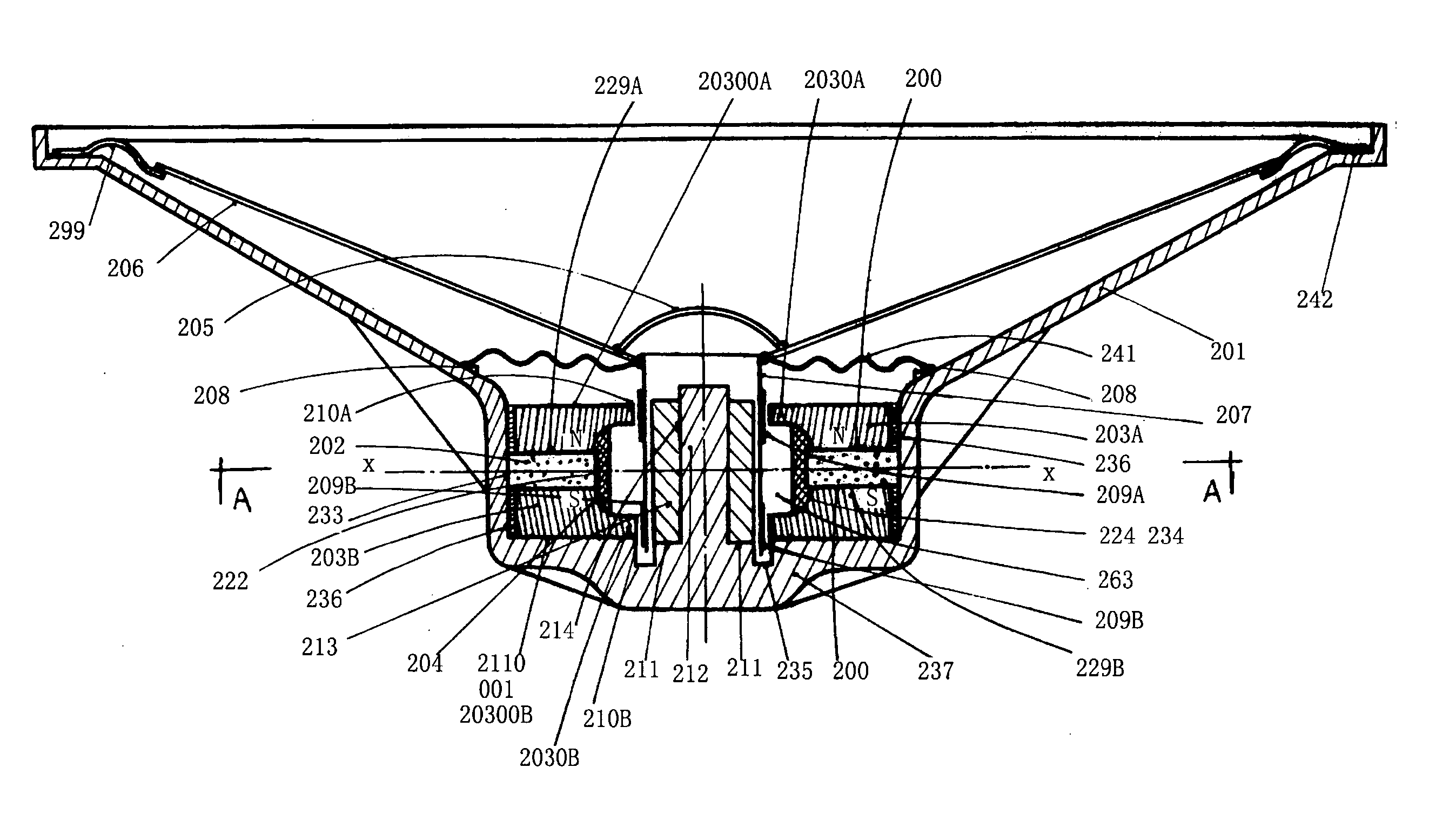
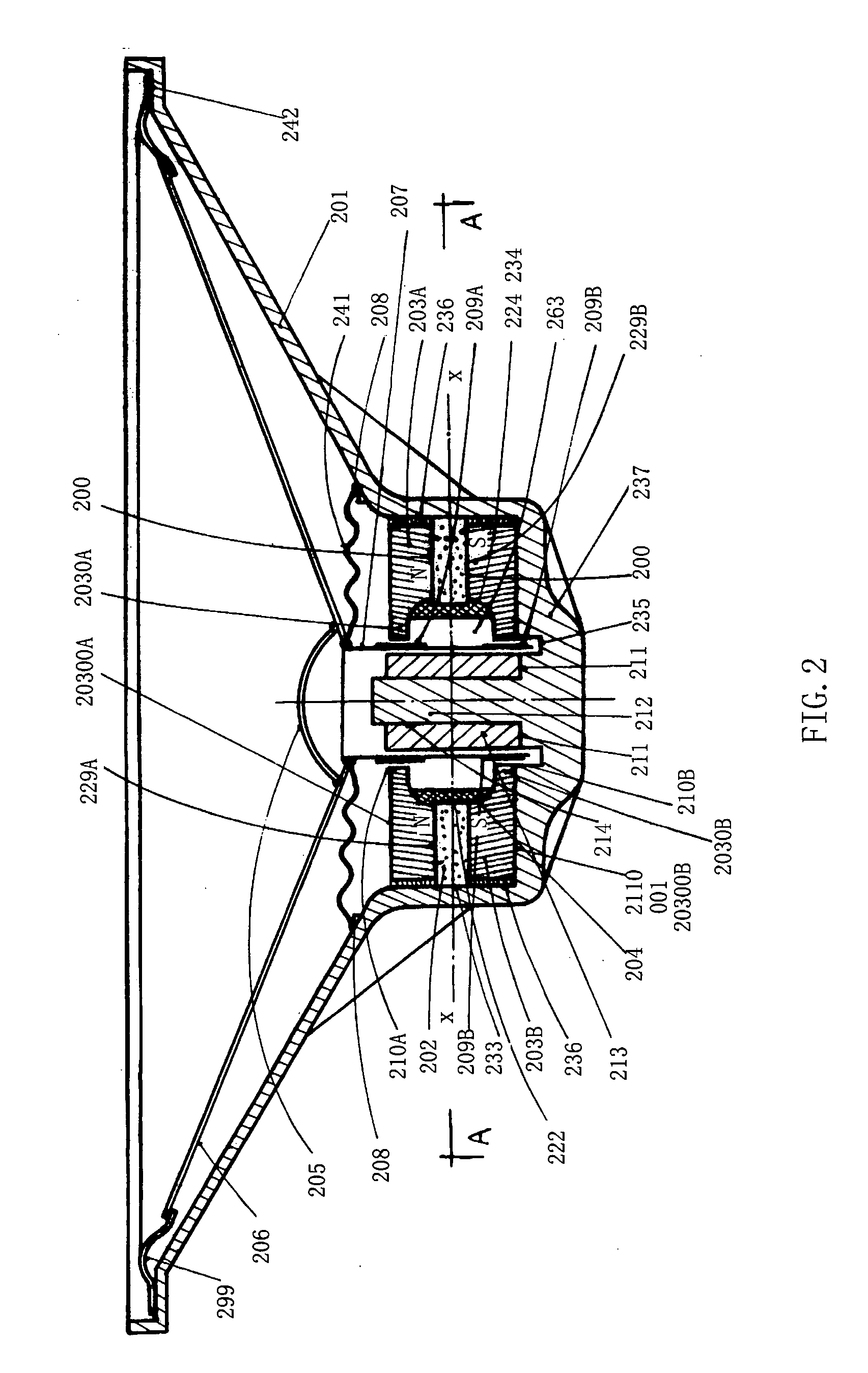
[0215]FIG. 2 shows the longitudinal section view of the loudspeaker of the invention.

[0216] The upper pole plate 203A and the lower pole plate 203B are two circular inwardly concave plates with equal projected planes and symmetrically disposed. A boss face 20300 with a central shaft hole 210 in the central portion is provided at the outer side of each concave plate. The convex periphery pole shoes 229A and 229B are disposed on the inner periphery of the upper pole plate 203A and lower pole plate 203B. The hollow frame 204 of non-magnetic material is embedded between the upper pole plate 203A and the inner profile face 224 of the lower pole plate 203B. The outer profile face 234 of the hollow frame 204 and the inner profile face 224 of the upper and lower pole plates are engaged with each other and applied with adhesive 001. The outer vertical face 222 with adhesive 001 applied there to in advance is provided in the middle of the outer profile of the hollow frame 204. The inner vert...

embodiment 3

[0234]FIG. 4 shows the plan section view of the magnetic path A-A of the

[0235] The upper pole plate 803A and lower pole plate 203B of the transducer are two coaxial and symmetric round concave plates. The permanent magnet 802 is an annular neodymium magnet embedded between the pole faces 800 of the periphery pole shoes 829A and 829B of the pole plates. Three uniformly spaced through holes 806 on the boss face 804 of the upper pole plate and three corresponding threaded holes 807 on the boss face 804 of the lower pole plate are for use of three non-magnetic fasteners to connect the magnetic path of the driver of the transducer. The hollow frame 804 is omitted in the fig.

embodiment 1

[0236] The rest is similar to that of the embodiment 1, so it is not repeated here.


PUM


Abstract

A transducer with dual coil and dual magnetic gap of which the upper and lower pole plates of are two inwardly concave plates or round plates. A set or more than1 a piece sets of axially magnetized permanent magnets are provided. Said permanent magnets are engaged with pole faces of said plates. Dual magnetic gap are formed between the vertical faces of said plates and the vertical faces of a coaxial mounted annular or cylindrical magnetic body. Coils are inserted into said magnetic gap, while wound direction of dual coil and the direction of current are decided to produce an electrodynamic force in the coils to the same direction. Said transducer possesses resistance load characteristics by setting the values of the inductance of the dual coil equal to each other in case that said transducer are provided with two magnetic paths and coil circuits completely symmetric in their magnetic characteristics.

Description

RELATED APPLICATIONS [0001] This application is a continuation-in-part of U.S. application Ser. No. 10 / 369,141 filed Feb. 18, 2003, the contents of which are incorporated herein by reference.FIELD OF INVENTION [0002] The present invention is related to an audio transducer, especially to a transducer with two coaxial magnetic gaps of the same diameters and dual coil belonged to the field of audio transducer in electricity. BACKGROUND OF THE INVENTION [0003] In the prior art JP6-233380A had supposed a loudspeaker with dual magnetic gap and dual coil which has disadvantages of bulk volume, low sensitivity while the inductance of dual coil cannot be cancelled and the loudspeaker remains a non-linear element with undesirable fidelity. [0004] The main disadvantages of the loudspeaker with two voice coils and two magnetic field presented by CN94246701.9 are: relatively large volume, low sensitivity while the inductance of dual coil cannot be cancelled with short axial strokes of the coil n...

Claims


Application Information

Patent Timeline
Patent Type & Authority Applications(United States)
IPC IPC(8): H02K16/02H02K33/18H04R9/02H04R9/04
CPCH02K16/02H02K33/18H04R2209/041H04R9/046H04R9/063H04R9/025
Inventor ZHANG, FAN
Owner ZHANG FAN
Why Eureka
Try Eureka