Reflection space image based rendering

a technology of reflection space and image, applied in the field of computer graphics, can solve the problems of significant loss in complexity and quality, loss of quality advancement, and inability to dynamically change synthetic objects, etc., and achieve the effect of extending the class of renderings

Inactive Publication Date: 2005-05-12
MICROSOFT TECH LICENSING LLC
View PDF5 Cites 35 Cited by
  • Summary
  • Abstract
  • Description
  • Claims
  • Application Information

AI Technical Summary

Benefits of technology

[0017] There are at least two contributions made by the present invention. The first is the application of IBR techniques in reflection space. This is called reflection space IBR—even though the invention does not necessarily operate on normal images, nor is the result a rendered image. Second is our hybrid rendering algorithm. The algorithm of the present invention and the nature of the source radiance environment maps allows new surface reflectances (e.g., BRDFs) and new geometry not found in the original source images to be used—thus extending the class of renderings possible with interactive IBR algorithms.

Problems solved by technology

The outstanding rendering challenge now becomes how to increase the performance of sophisticated shading algorithms without losing the advancements made in quality.
Traditionally, this has been accomplished by vastly simplifying the approximations used in the shading and lighting equations—resulting in a significant loss in complexity and quality.
This works well for predefined scenes or images, but not for dynamically changing synthetic objects.

Method used


Image

  • Reflection space image based rendering
  • Reflection space image based rendering
  • Reflection space image based rendering

Examples


Embodiment Construction

Table of Contents

[0031] 0. Overview and Terminology

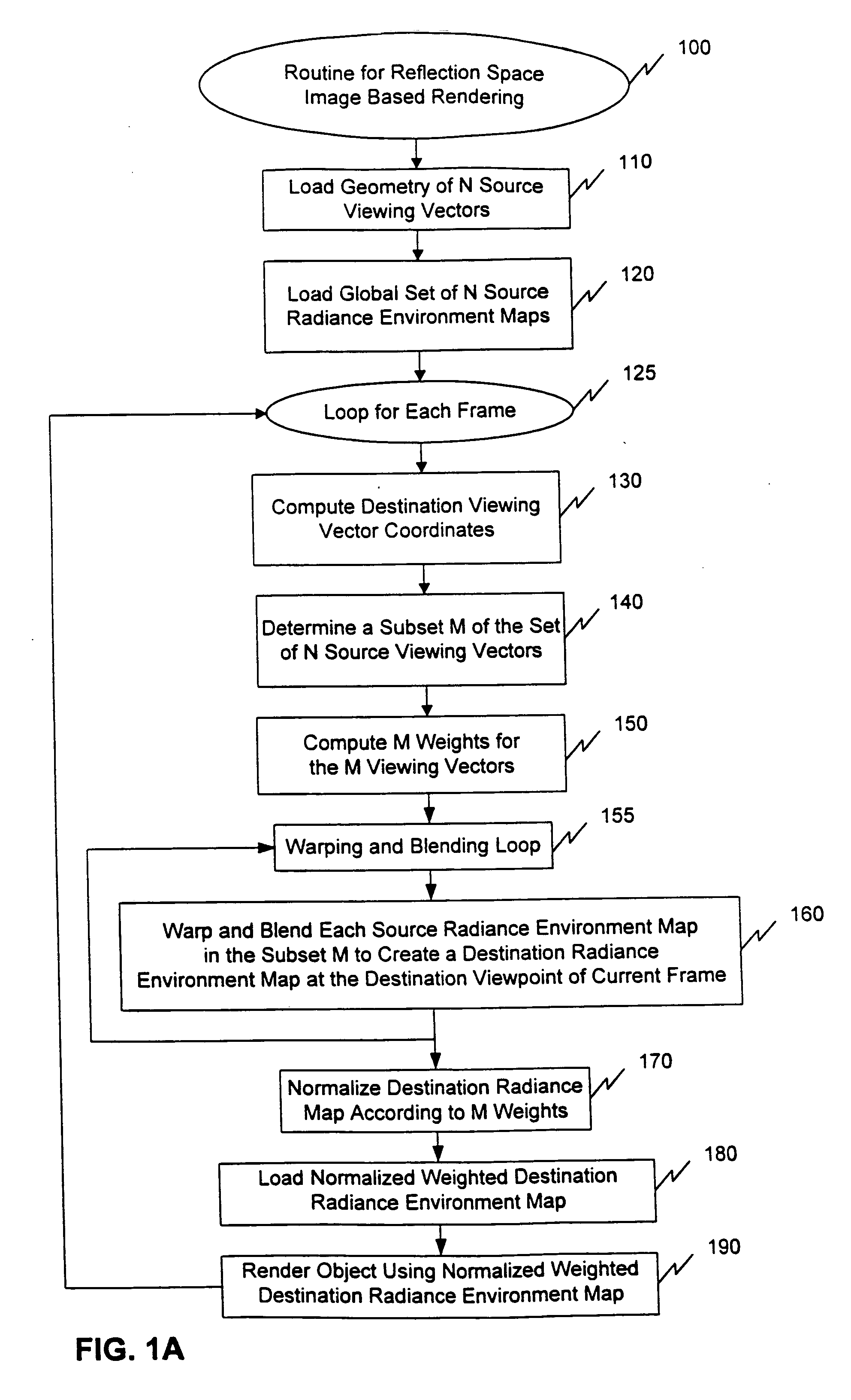
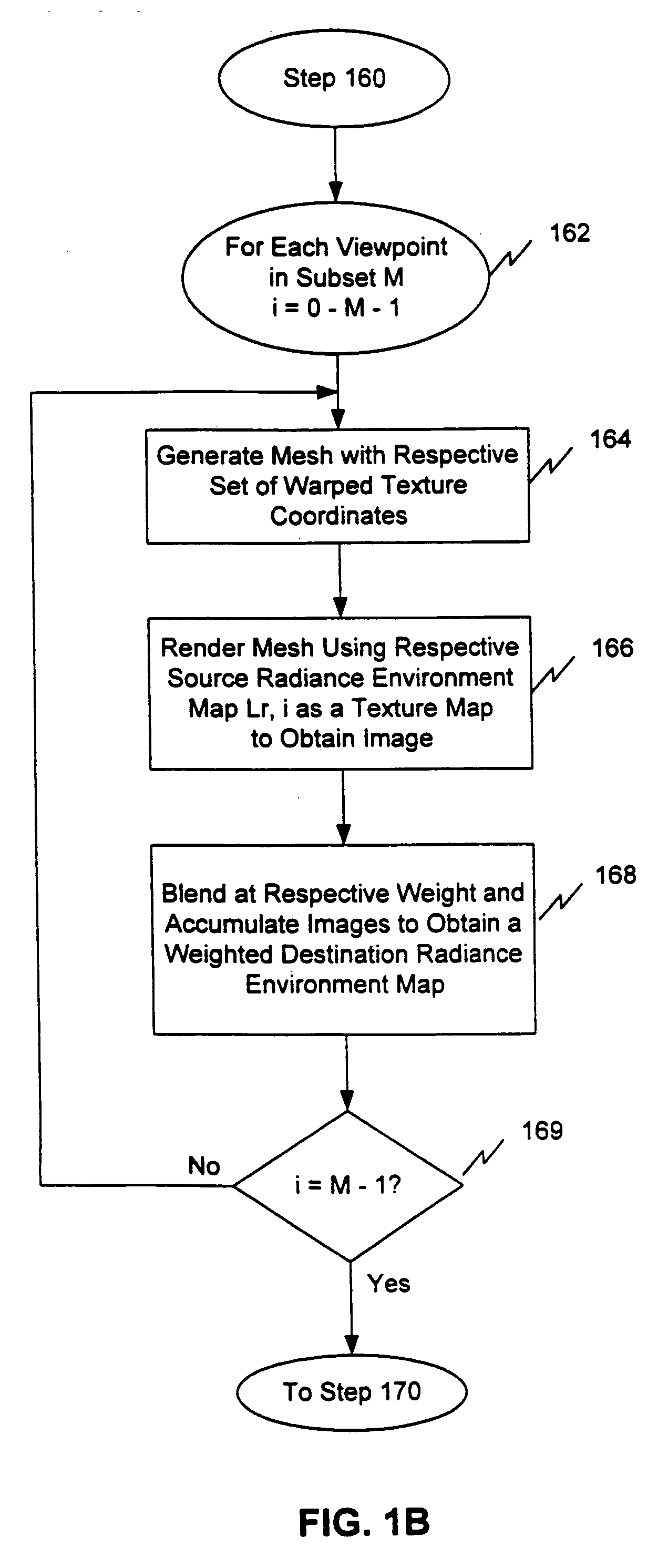
[0032] 1. Routine for Reflection-Spaced Image-Based Imaging [0033] 1.1 Set-up [0034] 1.2 Viewpoint Tracking Loop [0035] 1.3 Warping and Blending Loop

[0036] 2. Radiance Environment Maps [0037] 2.1 Obtaining Radiance Environment Maps

[0038] 3. Reflection Space IBR [0039] 3.1 Sampling View Directions [0040] 3.2 Map Warping [0041] 3.3 Specific Warps [0042] 3.4 Spherical Barycentric Interpolation

[0043] 4. Rendering Algorithm

[0044] 5. Examples 6. Example Implementations

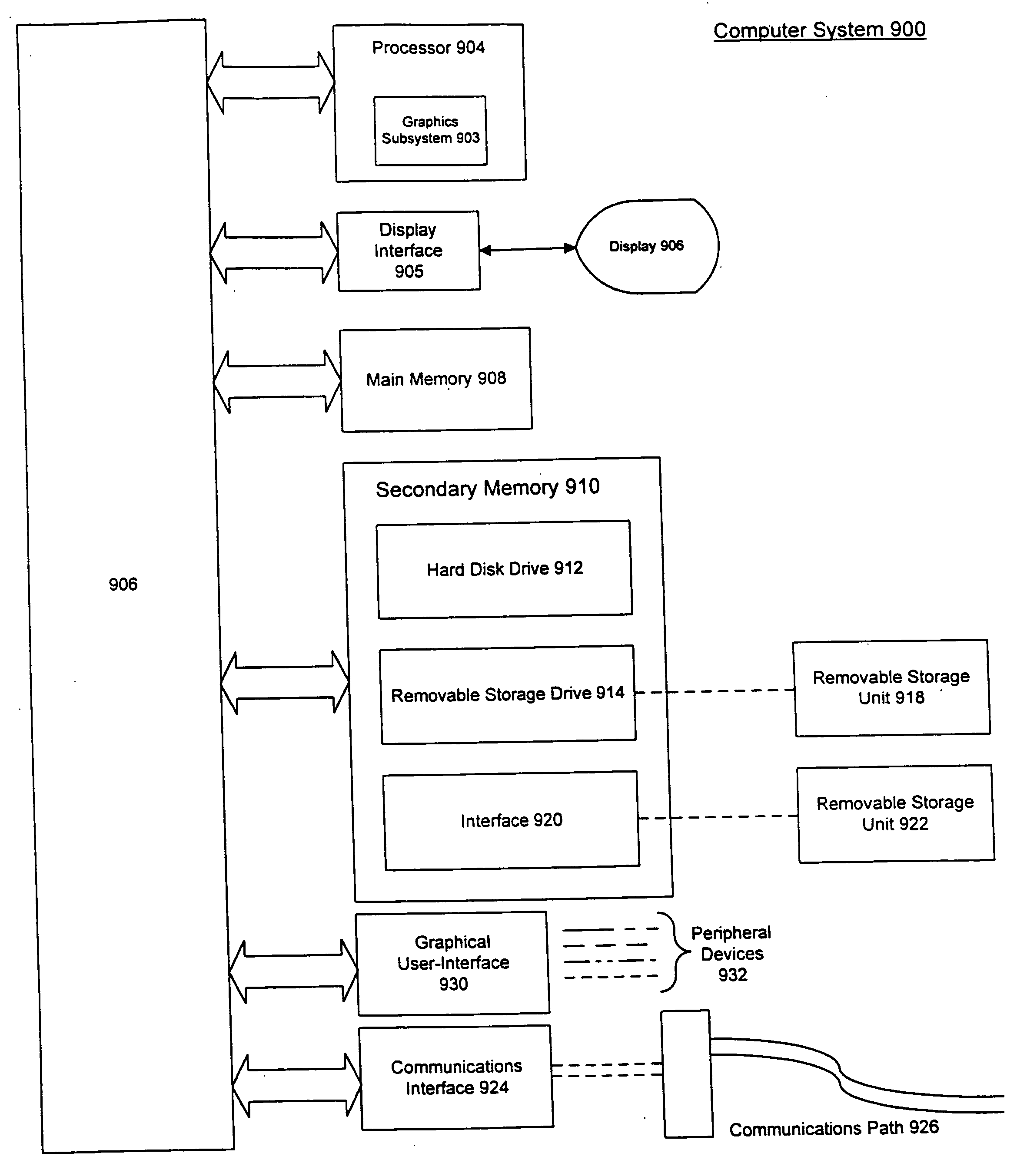
[0045] 7. Example GUI Computer System

[0046] 8. Conclusion

0. Overview and Terminology

[0047] High quality, physically accurate rendering at interactive rates has widespread application, but is a daunting task. The present invention bridges the gap between high quality offline and interactive rendering by using existing environment mapping hardware in combination with a new Image Based Rendering (IBR) algorithm. One aspect of the present invention lies in performing ...


PUM


Abstract

The present invention provides a method, system, and computer program product for reflection space image based rendering of an object at an interactive frame rate. A set of source radiance environment maps associated with a set of source viewing vectors are warped to create a destination radiance environment map associated with a destination viewing vector in a current frame. Blending and weighting operations can also be applied in creating the final destination radiance environment map. An object is then rendered with texture environment mapped from the destination radiance environment map.

Description

BACKGROUND OF THE INVENTION [0001] 1. Field of the Invention [0002] The present invention relates to the field of computer graphics. [0003] 2. Related Art [0004] Offline rendering algorithms have to a great extent conquered physically accurate photo-realism and complex synthetic shading. A result of over twenty years of research, these techniques all solve the lighting or rendering equation in some manner. See, the techniques in Blinn, J. F. and Newell, M. E., Comm. ACM 19:542-546 (1976); Cook, R. L., et al., “The Reyes image rendering architecture,” in Computer Graphics (SIGGRAPH '87 Proc.), vol. 21, Stone, M. C., ed., (July 1987), pp. 95-102; Debevec, P., “Rendering synthetic objects into real scenes: Bridging traditional and image-based graphics with global illumination and high dynamic range photography,” in SIGGRAPH 98 Conf Proc., Cohen, M., ed., Annual Conference Series, ACM SIGGRAPH, Addison Wesley (July 1998), pp. 189-198; He, X. D., et al, “A comprehensive physical model fo...

Claims


Application Information

Patent Timeline
Patent Type & Authority Applications(United States)
IPC IPC(8): G06T15/50
CPCG06T15/04G06T15/506G06T15/205
Inventor CABRAL, BRIAN KEITHOLANO, MARCNEMEC, PHILIP
Owner MICROSOFT TECH LICENSING LLC
Why Eureka
Try Eureka