Disk drive spindle motor with radial inward thrust area annular prutruding portion and bearing member communicating passage

Active Publication Date: 2005-05-12
NIDEC CORP
View PDF5 Cites 29 Cited by
  • Summary
  • Abstract
  • Description
  • Claims
  • Application Information

AI Technical Summary

Benefits of technology

[0022] This configuration makes it possible to prevent incidents of negative pressure and over-lift in a spindle motor utilizing dynamic-pressure bearings having a full-fill structure.
[0023] The fact either axial end of the bearing clearance formed in between the inner peripheral surface of the bearing hole and the circumferential surface of the shaft communicate by means of the passage enables the oil to redistribute itself within the bearing clearances. Thus even in cases in which a pressure difference has occurred between the axial upper and lower ends of the oil retained in between the inner peripheral surface of the bearing member and the circumferential surface of the shaft, arising from dimensional margin of error in the dynamic-pressure-generating grooves provided in the radial bearing section, or because some factor is off in processing the inner peripheral surface of the bearing hole or the circumferential surface of th

Problems solved by technology

With dynamic-pressure bearings in a full-fill structure, when the rotor a begins rotating, pumping by the dynamic-pressure-generating grooves d1, d1 and g1, g1 acts to draw oil in toward the center areas of each of the radial bearing sections d, d and thrust bearing sections g, g, peaking the fluid dynamic pressure in the bearing center areas; but the downside of this is that along the bearing edge areas the oil internal pressure drops.
This leakage impairs the endurance and reliability of the spindle motor.
Negative pressure occurring within the oil can also lead to the dynamic-pressure-generating grooves coming into contact with air bubbles, which invites vibration incidents and deterioration due to NRRO (non-repeatable run-out).
Such consequences impair the rotational precision of the spindle motor.
Incidents of over-lift on the rotor give rise to frictional wear on the thrust plate and the sleeve by bringing them into contact; frictional wear is

Method used


Image

  • Disk drive spindle motor with radial inward thrust area annular prutruding portion and bearing member communicating passage
  • Disk drive spindle motor with radial inward thrust area annular prutruding portion and bearing member communicating passage
  • Disk drive spindle motor with radial inward thrust area annular prutruding portion and bearing member communicating passage

Examples


Embodiment Construction

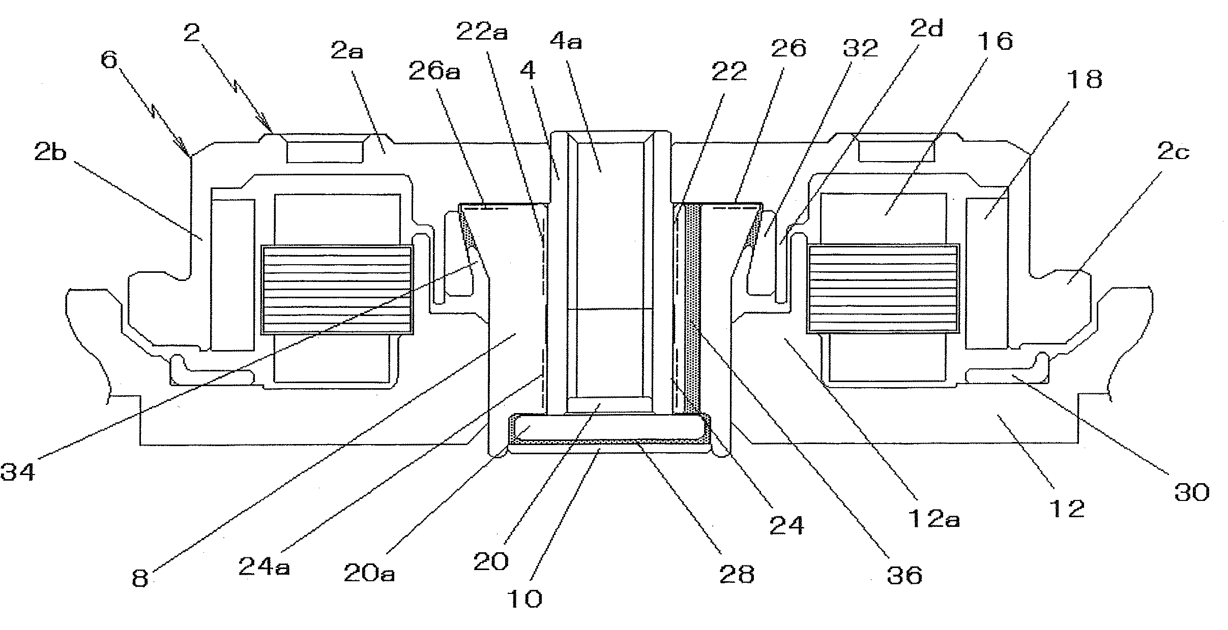
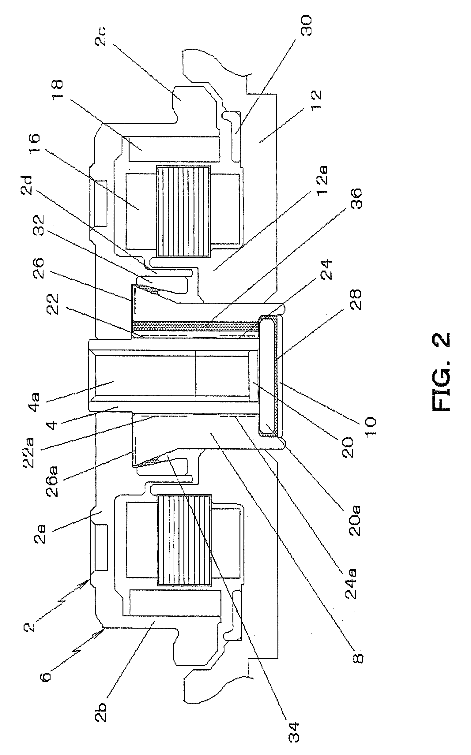
[0034] Embodiments according to the present invention of a spindle motor and of a disk drive equipped therewith will be explained in the following with reference to FIGS. 2 through 6, but the present invention is not limited to the embodiments set forth below. It will be appreciated that although for the sake of convenience in the description of the present embodiments, “upper / lower, above / below, etc.” are in the vertical direction of the drawings, the orientation of the spindle motor in its actually installed state is not limited.

[0035] (1) Configuration of Spindle Motor

[0036] The spindle motor graphically represented in FIG. 2 is furnished with: a rotor 6 constituted from a rotor hub 2 which is made up of a an approximately disk-shaped upper wall portion 2a (top plate) and a cylindrical peripheral wall portion 2b (cylindrical wall) depending downward from the outer rim of the upper wall portion 2a—and from a shaft 4 one end portion of which perimetrically is fixedly fitted into ...


PUM


Abstract

In a spindle motor utilizing dynamic-pressure bearings having a full-fill structure, a bearing configuration that balances and sustains at or above atmospheric pressure the internal pressure of the bearing oil. Thrust and radial bearing sections are configured within oil-filled bearing clearances in between the rotor, the shaft, and a shaft-encompassing hollow bearing member. A communicating passage one end of which opens on, radially inwardly along, the thrust bearing section is formed in the bearing member. Either axial ends of the bearing clearance in between the bearing member and shaft communicate through the passage. The communicating passage enables the oil to redistribute itself within the bearing clearances. Pressure difference between the axial upper and lower ends of the oil retained in between the bearing member and the shaft is compensated through the communicating passage, preventing incidents of negative pressure within the oil and of over-lift on the rotor. And an annular protruding portion is formed on at least one of the end face of the bearing member and the flat face of the rotor at radially inward portion of the thrust bearing section.

Description

BACKGROUND OF INVENTION [0001] 1. Technical Field [0002] The present invention relates to spindle motors employing dynamic-pressure bearings in which oil is the working fluid, and to disk drives equipped with such spindle motors. The invention relates in particular to miniature, low-profile spindle motors that drive recording disk 2.5 inches and under, and to disk-drives equipped with such spindle motors. [0003] 2. Description of the Related Art [0004] Dynamic-pressure bearings in which the fluid pressure of a lubricating fluid such as oil interposed in between the shaft and the sleeve is exploited in order to support the two letting the one rotate against the other have been proposed to date as bearings for spindle motors employed in disk drives that drive hard disk and like recording disks. [0005]FIG. 1 depicts one example of a spindle motor employing dynamic-pressure bearings. This spindle motor in which conventional dynamic pressure bearings are employed is configured with a pai...

Claims


Application Information

Patent Timeline
IPC IPC(8): G11B17/02G11B17/022G11B25/04G11B33/12H02K7/08
CPCF16C17/102F16C33/107G11B33/121G11B17/022G11B25/043F16C33/1085F16C17/045F16C17/107F16C2370/12
Inventor NISHIMURA, HIDEKIOKU, YOSHITOMORI, YASUHIRO
Owner NIDEC CORP
Why Eureka
Try Eureka