Pseudo-frames for MPEG-2 encoding

a pseudo-frame and encoding technology, applied in the field of real-time video encoding, can solve the problem that the mpeg-2 syntax does not support variable frame ra

Active Publication Date: 2005-05-12
ARCSOFT
View PDF10 Cites 24 Cited by
  • Summary
  • Abstract
  • Description
  • Claims
  • Application Information

AI Technical Summary

Problems solved by technology

However, MPEG-2 syntax does not support variable frame rates.

Method used


Image

  • Pseudo-frames for MPEG-2 encoding
  • Pseudo-frames for MPEG-2 encoding
  • Pseudo-frames for MPEG-2 encoding

Examples


Embodiment Construction

[0015] In accordance with the invention, a method is provided to simulate frame skipping in MPEG-1 and MPEG-2 coding by encoding a P-frame or a B-frame as a pseudo-frame that completely references one reference frame of the frame being replaced. This method can be used to improve encoding speed in real-time video applications having limited hardware resources. In addition, this method can also handle VBV buffer overflow and underflow for bit-rate control. Overall, this method provides a smooth video even when the scenes change frequently and the processing power is limited.

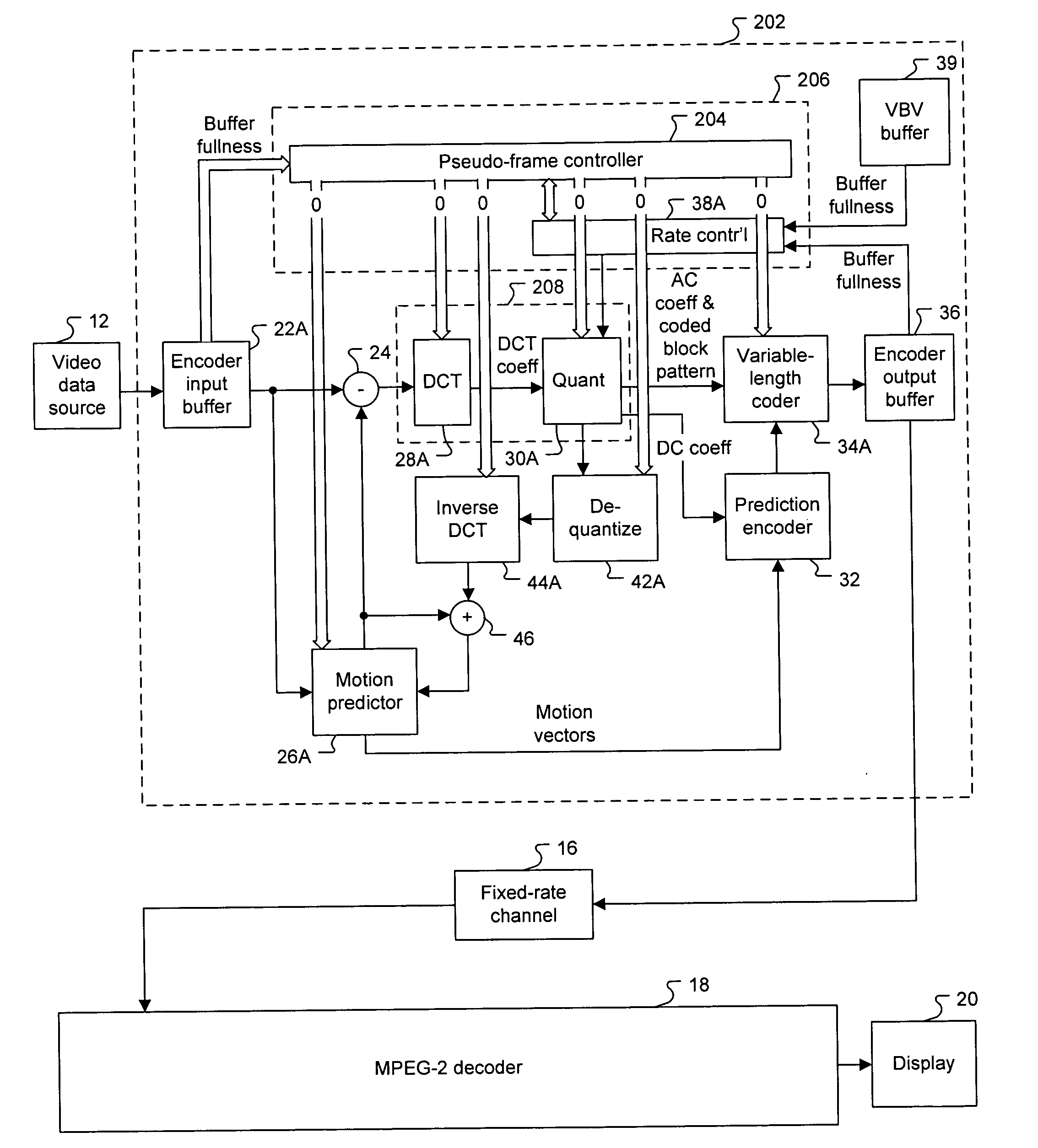
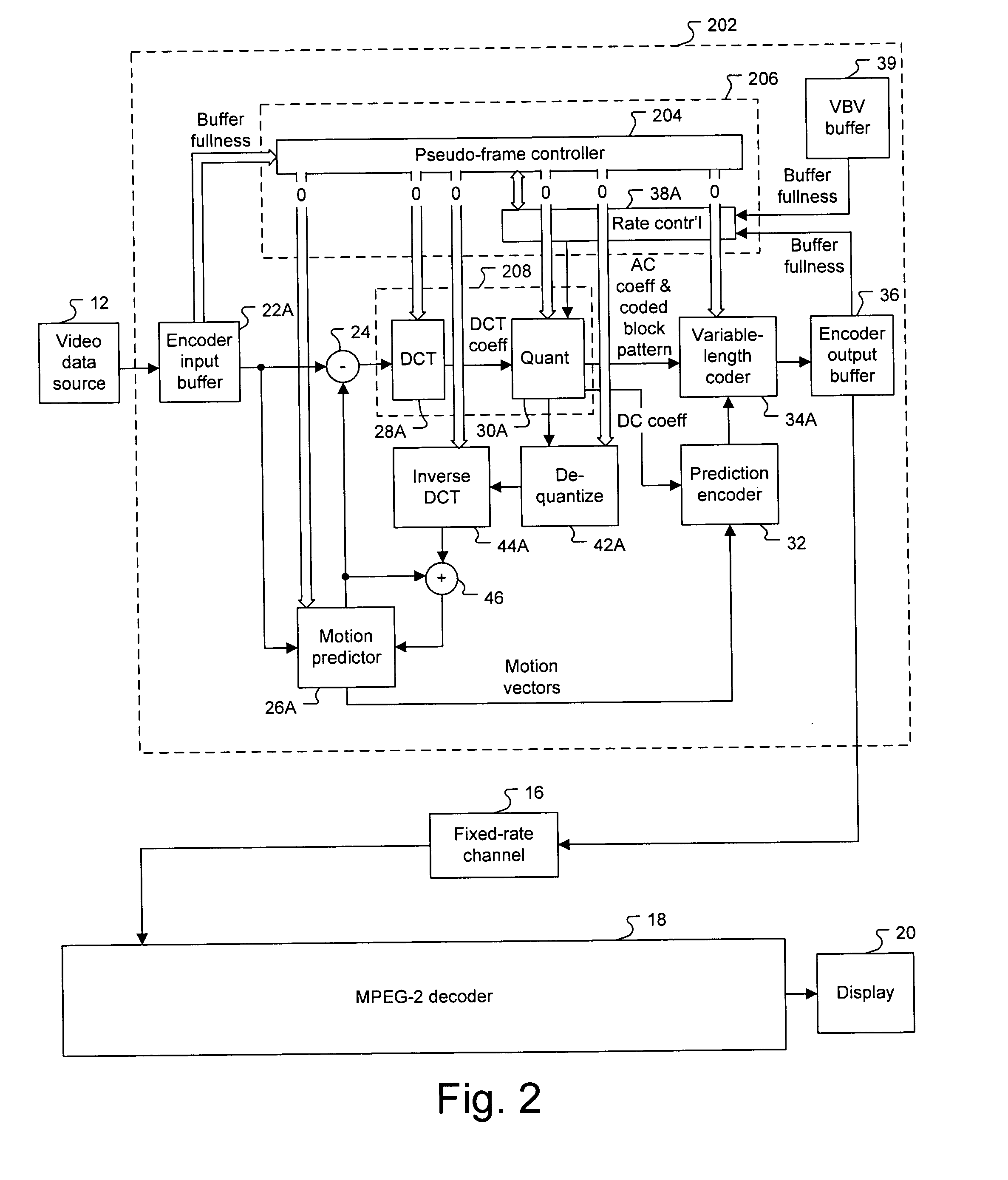
[0016]FIG. 2 illustrates a video encoder 202 with pseudo-frame control in one embodiment of the invention. Encoder 202 includes a pseudo-frame controller 204 that communicates with encoder input buffer 22A, motion predictor 26A, DCT coder 28A, quantization coder 30A, VLC 34A, rate controller 38A, de-quantization coder 42A, and inverse DCT coder 44A. Typically, the motion predictor is also referred to as a tempora...


PUM


Abstract

A method for real-time video encoding includes buffering frames in an encoder input buffer, retrieving the frames from the encoder input buffer, encoding the retrieved frames into a bit stream, monitoring the encoder input buffer for buffer overflow, and, if the encoder input buffer is about to overflow, encoding one of the retrieved frames as a pseudo-frame that completely references one reference frame of the one retrieved frame. Encoding one of the retrieved frames as a pseudo-frame bypasses a majority of the encoding procedures to improve the overall encoding speed. The method further includes monitoring a hypothetical decoder input buffer that models an actual decoder input buffer in a video decoder, encoding one of the retrieved frames with a pseudo-frame if the hypothetical decoder input buffer is about to underflow, and adding stuffing bits to the bit stream if the hypothetical decoder input buffer is about to overflow.

Description

FIELD OF INVENTION [0001] This invention relates to real-time video encoding, and more particularly to systems and methods for MPEG-1 and MPEG-2 video applications. DESCRIPTION OF RELATED ART [0002]FIG. 1 illustrates a conventional MPEG system. A video data source 12 outputs a video sequence to a MPEG video encoder 14. Video encoder 14 converts frame by frame of the video sequence, which are each segmented into 16 by 16 arrays of pixel data called macroblocks, into a bit stream that complies with the MPEG-1 or the MPEG-2 standards. The bit stream is transported over a fixed-rate channel 16 to a MPEG video decoder 18. Video decoder18 converts the bit stream into frames that are outputted to a display 20. [0003] Video encoder 14 includes an encoder input buffer 22 that stores the frames until they are processed. There are two modes in video coding: non-prediction (“intra”) mode and prediction (“inter”) mode. In intra mode, the macroblocks in the frame being coded are not compared with...

Claims


Application Information

Patent Timeline
Patent Type & Authority Applications(United States)
IPC IPC(8): G06K9/36G06K9/46H04B1/66H04N7/12H04N7/26H04N7/46H04N7/50
CPCH04N19/159H04N19/172H04N19/46H04N19/577H04N19/61H04N19/132H04N19/152H04N19/15
Inventor WANG, XINGGUOCHEN, GUOBINZHOU, LINGXIANG
Owner ARCSOFT
Why Eureka
Try Eureka