
Dyed polymer coating for display panel

a technology of display panels and polymer coatings, applied in the field of panels, can solve the problems of reducing contrast, reducing brightness, and reducing the color transmission of plasma displays, and achieve the effect of improving the color balance and contrast of a pdp

Inactive Publication Date: 2005-05-12
JDS UNIPHASE CORP
View PDF4 Cites 72 Cited by
  • Summary
  • Abstract
  • Description
  • Claims
  • Application Information

AI Technical Summary

Benefits of technology

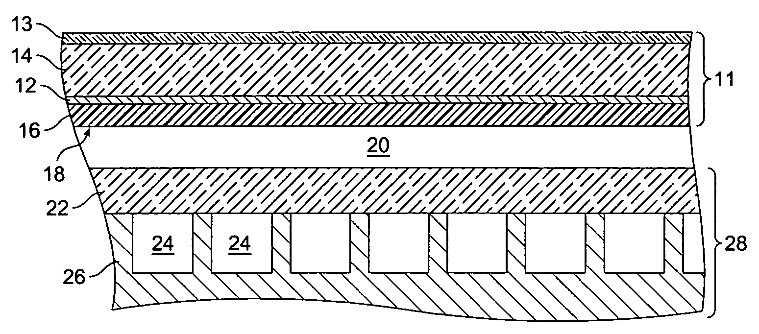
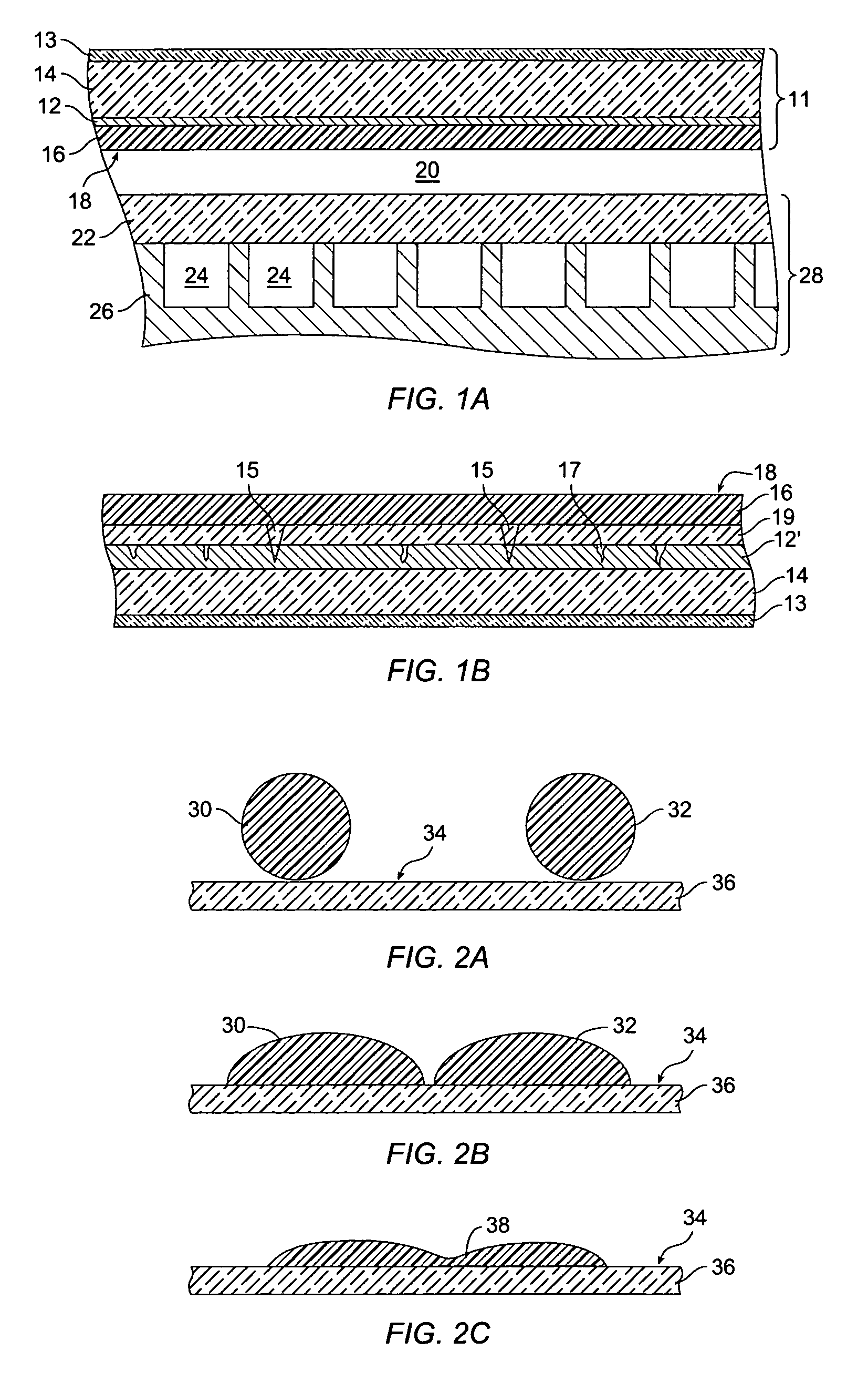
[0013] In one embodiment of the invention, a transmissive panel has a polymer coating dried on a substrate, such as a glass panel, to form a textured antireflective surface of the polymer coating. In a further embodiment, the polymer coating includes a dye, such as a dye to block light at 585 nm, and / or to block infrared light. In a particular embodiment, the polymer coating is formed form a water-based polymer system and the dye comprises a cyanine dye. Adding dye to the polymer solution can improve the color-balance and contrast of a PDP. For use in PDPs and similar applications, it is desirable that the polymer coating has a total thickness variation of not more than 5% to achieve a transmission variation substantially undetectable by an unaided human eye. Embodiments of the present invention enable large-format transmissive panels with polymer coatings having a textured anti-reflective surface, including curved or ridged panels.

Problems solved by technology

Unfortunately, neon, which is often used in the gas mixture for color PDPs, produces orange-red light at 585 nm, which can cause an imbalance in the color of the display and reduce contrast unless corrective measures are taken.
Many plasma displays currently being developed by various display manufactures have undesirably low brightness and low red, green and blue color transmission.
Therefore, neutral density filters cannot effectively be used for color and contrast enhancement in plasma display applications since neutral density filters would further reduce the brightness of the display.
To achieve truer color emissions from color plasma displays, circular polarizer-based contrast-enhancing filters are being used, even though such filters are quite expensive.

Method used


Image

  • Dyed polymer coating for display panel
  • Dyed polymer coating for display panel
  • Dyed polymer coating for display panel

Examples


Embodiment Construction

[0028] I. Introduction

[0029] A substrate is coated with a polymer solution containing a dye to form a dyed polymer coating on the substrate. As used herein, “dyed polymer” means a solution, including a solid state solution, of dye in a polymer matrix. It is generally desirable to keep the concentration of dye sufficiently low to avoid phase separation of the dye from the polymer. The dyed polymer coating provides improved safety, durability and optical performance. In one embodiment, the dyed polymer coating is sandwiched between the EMF filter and the light-emitting portion of a PDP. This configuration protects the dyed polymer coating, which in one embodiment is a notch filter for 585 nm light, from scratches. The dyed polymer coating also serves as a barrier to protect the EMF filter from environmental factors. The dyed polymer film also acts as a safety film to retard the formation of loose glass shards if the glass substrate shatters. In a further embodiment, thin-film layers ...


PUM

PropertyMeasurementUnit
Fractionaaaaaaaaaa
Thicknessaaaaaaaaaa
Lengthaaaaaaaaaa

Abstract

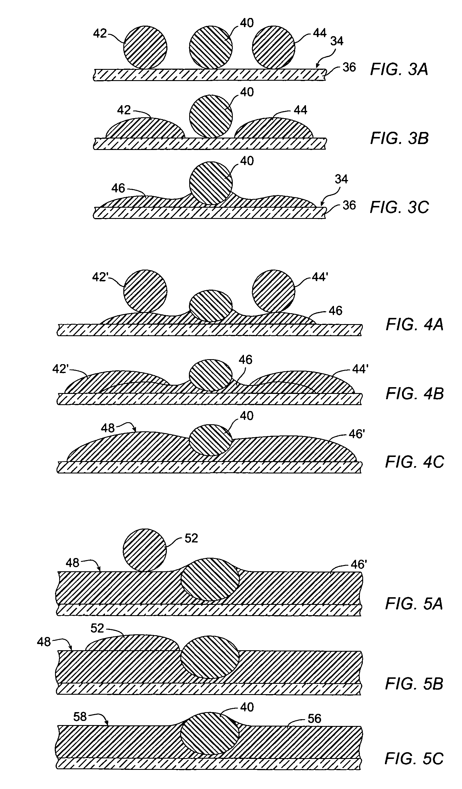
An transmissive panel includes a polymer coating with a textured antireflective surface. Texturing of the surface is achieved in a variety of fashions. In some embodiments the polymer coating is embossed after application to the panel. In other embodiments, the polymer coating is solvent-based and develops a textured surface as a result differential shrinkage. In yet other embodiments, an aerosol of solvent-based polymer precursor is applied to the surface as a combination of high-viscosity droplets and low-viscosity droplets, portions of high-viscosity droplets extending above a film of polymer formed from low-viscosity droplets to provide a textured antireflective surface.

Description

CROSS-REFERENCE TO RELATED APPLICATIONS [0001] This U.S. patent application is being concurrently filed with U.S. patent application Ser. No. ______, entitled METHOD OF APPLYING A UNIFORM POLYMER COATION, by Thomas Mayer, Hiren V. Shah, Brad A. Duffy, and Richard K. Zoborowski (Atty. Docket No. OC0323US), the disclosure of which is hereby incorporated in its entirety for all purposes. STATEMENT REGARDING FEDERALLY SPONSORED RESEARCH OR DEVELOPMENT [0002] Not applicable. REFERENCE TO MICROFICHE APPENDIX [0003] Not applicable. FIELD OF THE INVENTION [0004] The present invention relates generally to panels used in display systems, and more particularly to a polymer precursor that is applied to a panel in a liquid state and hardens into a polymer coating with an antireflective surface. BACKGROUND OF THE INVENTION [0005] Display panels are used in various display systems, such as television, computer, and portable electronic device displays and are typically made from glass or plastic su...

Claims


Application Information

Patent Timeline
IPC IPC(8): B32B17/10C03C17/00C03C17/32C03C17/34C09D175/04G02B1/11
CPCB32B17/10018B32B17/10339C03C17/007C03C17/32Y10T428/24355C03C2217/445C03C2217/77C09D175/04G02B1/111C03C17/34
Inventor MAYER, THOMASSHAH, HIREN V.DUFFY, BRAD A.ZOBOROWSKI, RICHARD K.
Owner JDS UNIPHASE CORP
Learn More