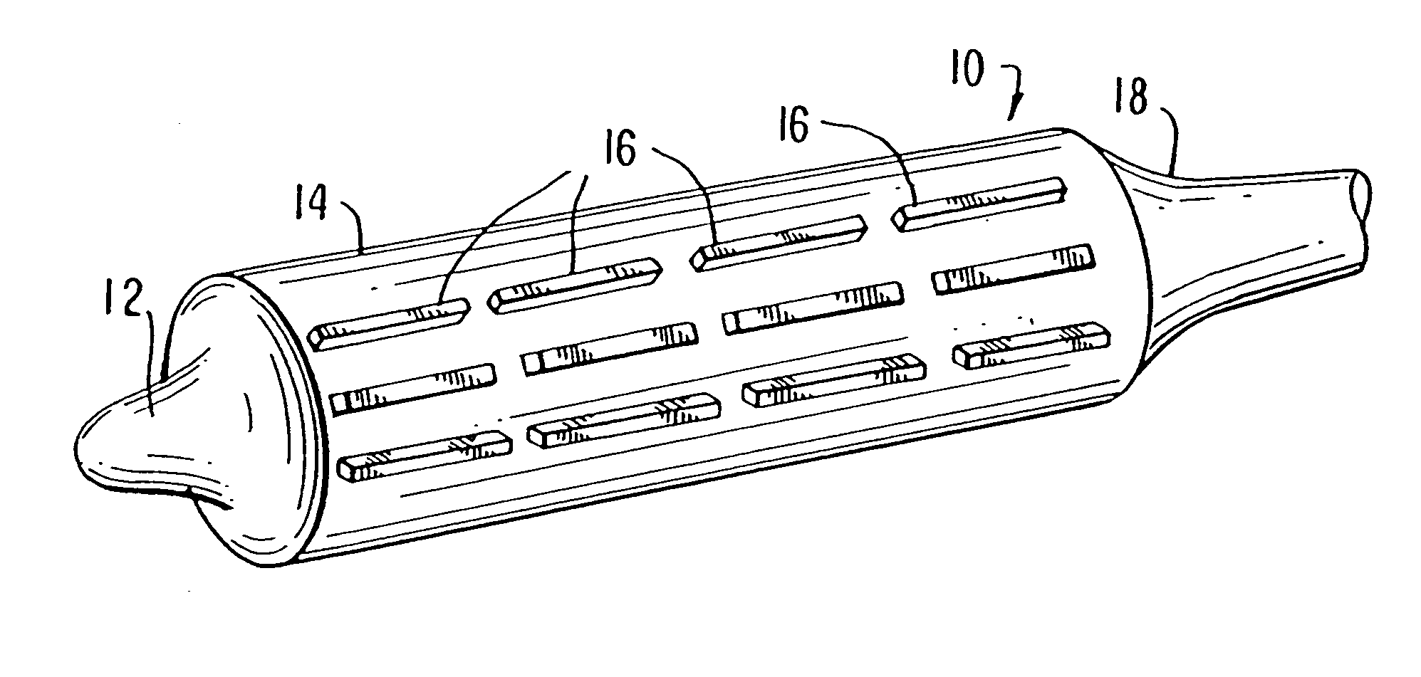
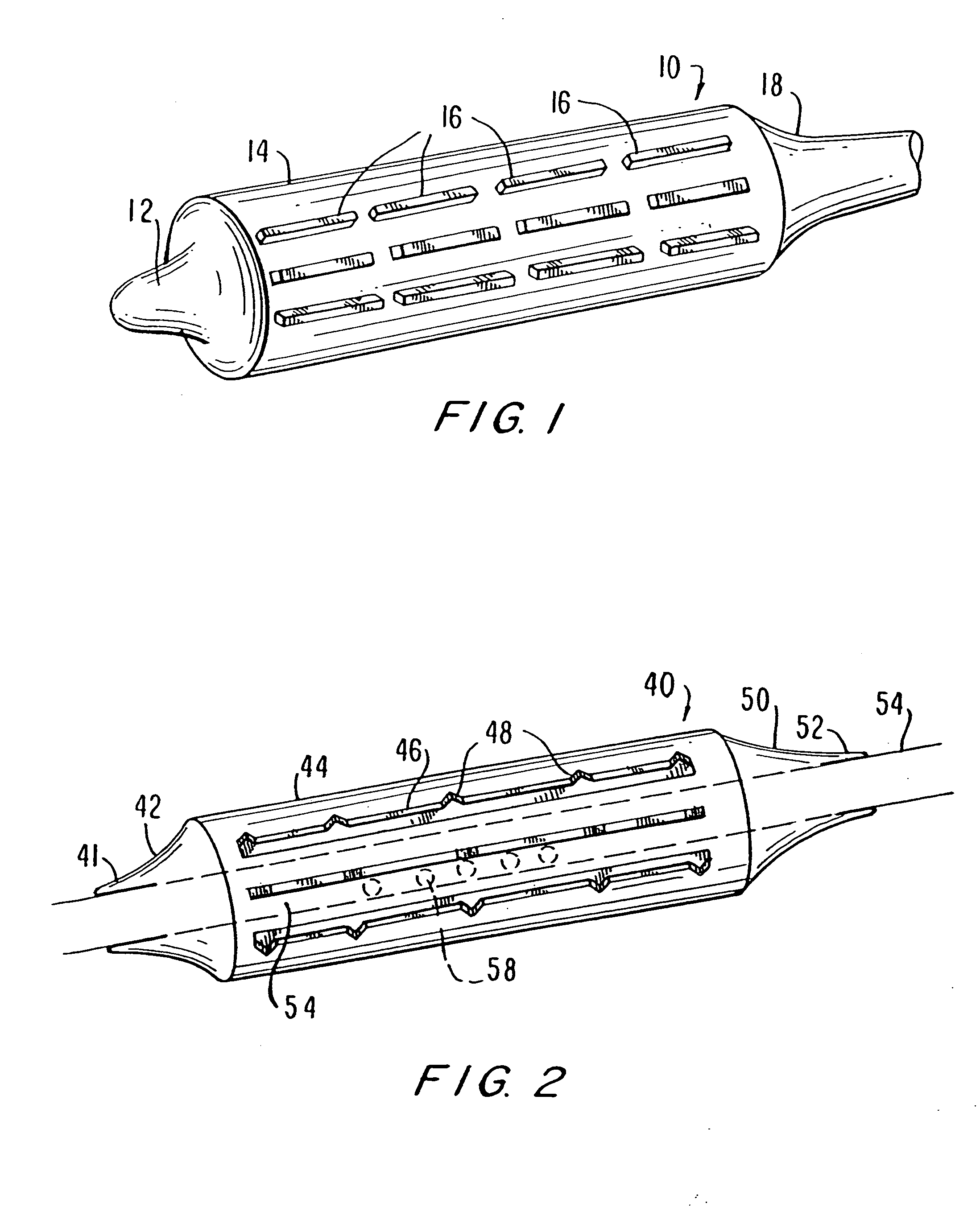
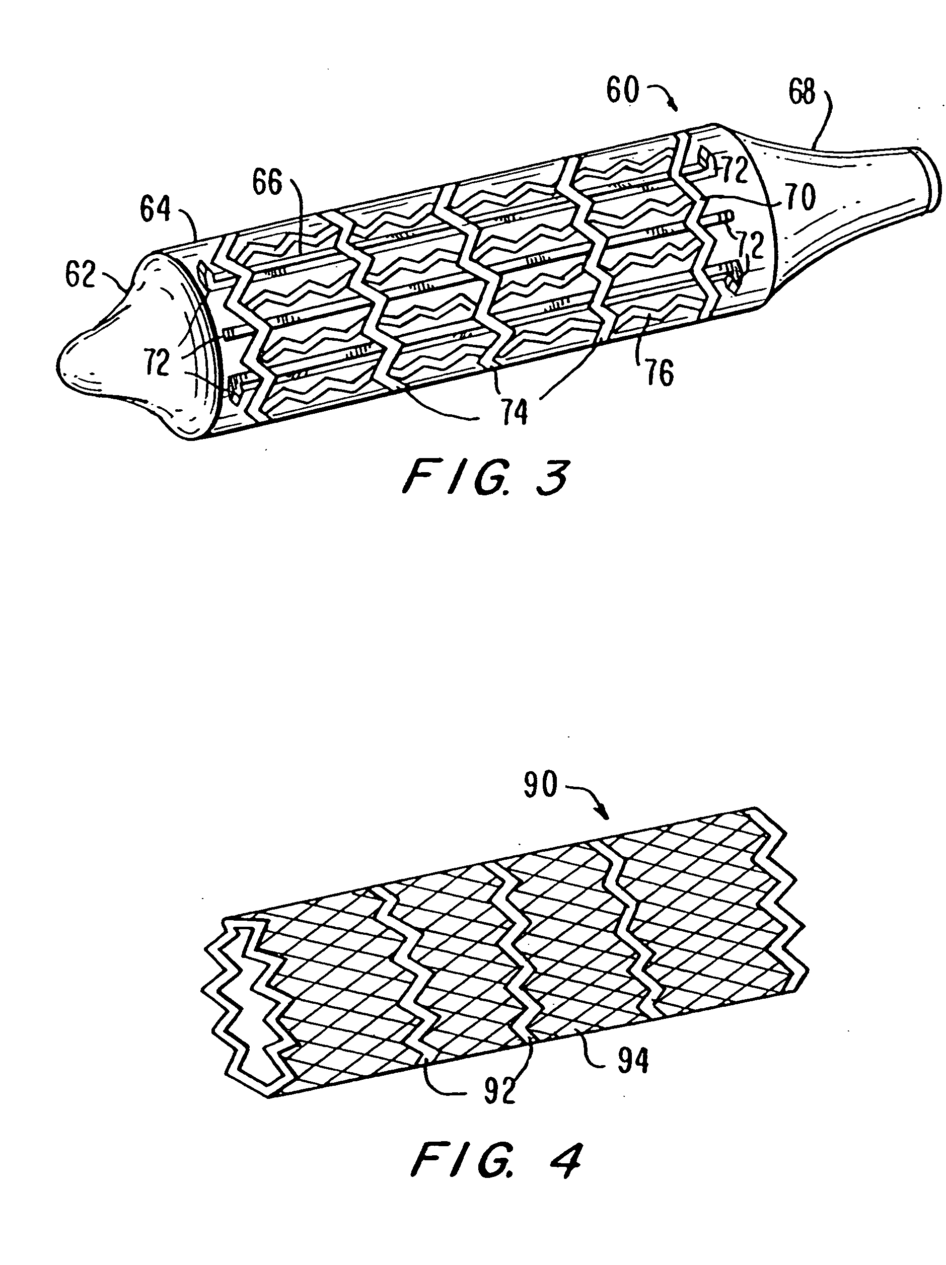
Unfortunately, currently available balloon systems for angioplasty and for delivery and expansion of stents often fail to properly deploy the stent to produce a uniform
diameter and cross-sectional area along the length of the stent.
However, the more rigid material still has an elastic limit.
Balloons made of such material and excessively inflated will be permanently deformed, and may eventually burst.
Such deformed balloons are much more difficult to remove from the patient.
Moreover, increasing the pressure in the balloon increases the potential for rupture and serious harm to the patient.
Even the use of higher pressures permitted by more rigid balloons are insufficient to dilate some arterial stenoses, particularly if they have an annular configuration.
Some residual stenoses and a non-uniform cross-sectional area along the length of the stent will result.
Another problem frequently encountered during
balloon dilation of stents is the occurrence of flaring of the stent at its ends.
The resulting different diameters of expansion are transferred to the stent causing a “trumpet-like” outward flaring of the stent at its ends, which is undesirable.
Additionally, there are several problems with the conventional methodology for delivering a stent to an occlusive site with a conventional
balloon catheter.
As the operator tries to advance or withdraw the
catheter, the calcified matter or other irregularity may catch hold of the stent and capture it in place while the
catheter is moved, causing the stent to separate from the balloon.
If the stent is displaced with respect to the balloon, slips partially off the balloon, or separates from the balloon entirely, then the stent will not deploy properly.
If the undeployed stent separates from the balloon entirely, retrieving the undeployed stent becomes a very serious problem.
Similarly, a stent that is only partially deployed or is incorrectly positioned presents a very
significant risk to the patient.
Where an occlusive site is only partially accessible by means of a conventional
balloon catheter, i.e., only one end of an
occlusion has an inner
diameter that is of sufficient size to receive a
balloon catheter, expansion of the balloon often causes the entire device to be squeezed and slip out of the occlusive site entirely.
Thus, attempts to open such partially accessible occlusive sites often fail.
Such force causes additional stress at the occlusive site and in surrounding structures which present a further risk of rupturing the
target site or causing damage to the surrounding areas.
The same difficulties are encountered in attempting to position and deploy a stent-graft with a conventional balloon
catheter.
Incomplete stent-graft deployment can result in troublesome endoleaks caused by inadequate or otherwise ineffective sealing of the stent-graft at the ends with the interior of the vessel.
Such endoleaks allow a channel of
blood flow to develop that bypasses the stent-graft, greatly reducing its effectiveness and potentially causing the stent-graft to migrate.
Where stent-grafts are deployed to exclude aneurysms, such as in the endovascular repair of an
abdominal aortic aneurysm, endoleaks are a very significant problem in that they may allow flow to an
aneurysm that could cause the
aneurysm to rupture.
Additionally, it has also been found that an inherent limitation of the balloon
catheter device described in U.S. Pat. No. 4,796,629 is its limited maneuverability for deployment in the vascular
system.
The stiffeners of such a device are fairly rigid, have a
fixed length in excess of the
turning radius needed to navigate certain pathways and have a fixed, although not necessarily uniform, cross-section.
As a result, it can be particularly difficult to navigate the device of U.S. Pat. No. 4,796,629 through the vascular
system to reach certain occlusions in smaller vessels without utilizing non-standard entry locations or invasive manual procedures for straightening tortuous vascular pathways.


