Sinuous composite connector system

a composite connector and composite technology, applied in the field of concrete sandwich walls, can solve the problems of low construction efficiency, high thermal conductivity, and high cost of construction, and achieve the effect of less skill and less construction cos

Inactive Publication Date: 2005-05-19
COMPOSITE TECH CO LLC
View PDF6 Cites 18 Cited by
  • Summary
  • Abstract
  • Description
  • Claims
  • Application Information

AI Technical Summary

Benefits of technology

[0016] A further objective of the present invention is the provision of a connection system for concrete sandwich walls that requires less skill and is less expensive to construct.

Problems solved by technology

Concrete sandwich wall panels are subject to lateral forces such as wind and seismic load, gravity loads, and temperature-induced forces.
These trusses, however, are susceptible to corrosion damage and have a very high thermal conductivity.
Sandwich panels made with these metal trusses therefore have a suspect service life and provide relatively low thermal performance.
Although the uncracked stiffness of such panels will be nearly the same as for a composite panel, partially composite panels will tend to crack at lower loads than composite panels.
Although composite and partially composite walls are much more efficient than non-composite walls in resisting normal horizontal forces, the connection system's enforcement of strain compatibility between the concrete layers can create undesirable behaviors.
The thermal barrier must, therefore, lead to significant temperature differentials between the two concrete layers.
While this can be primarily an aesthetic problem, it can also lead to failure of the sealant at the joints between panels.
Also, in many applications, both composite and partially composite panels have excess capacity.
Although non-composite wall panels are generally too flexible or have insufficient strength to safely resist wind loads, many composite and partially composite wall panels have excess capacity and suffer from thermal and differential pre-stress bowing.
The disadvantage of this system is that the concrete is must carry the forces, not the connectors.

Method used


Image

  • Sinuous composite connector system
  • Sinuous composite connector system
  • Sinuous composite connector system

Examples


second embodiment

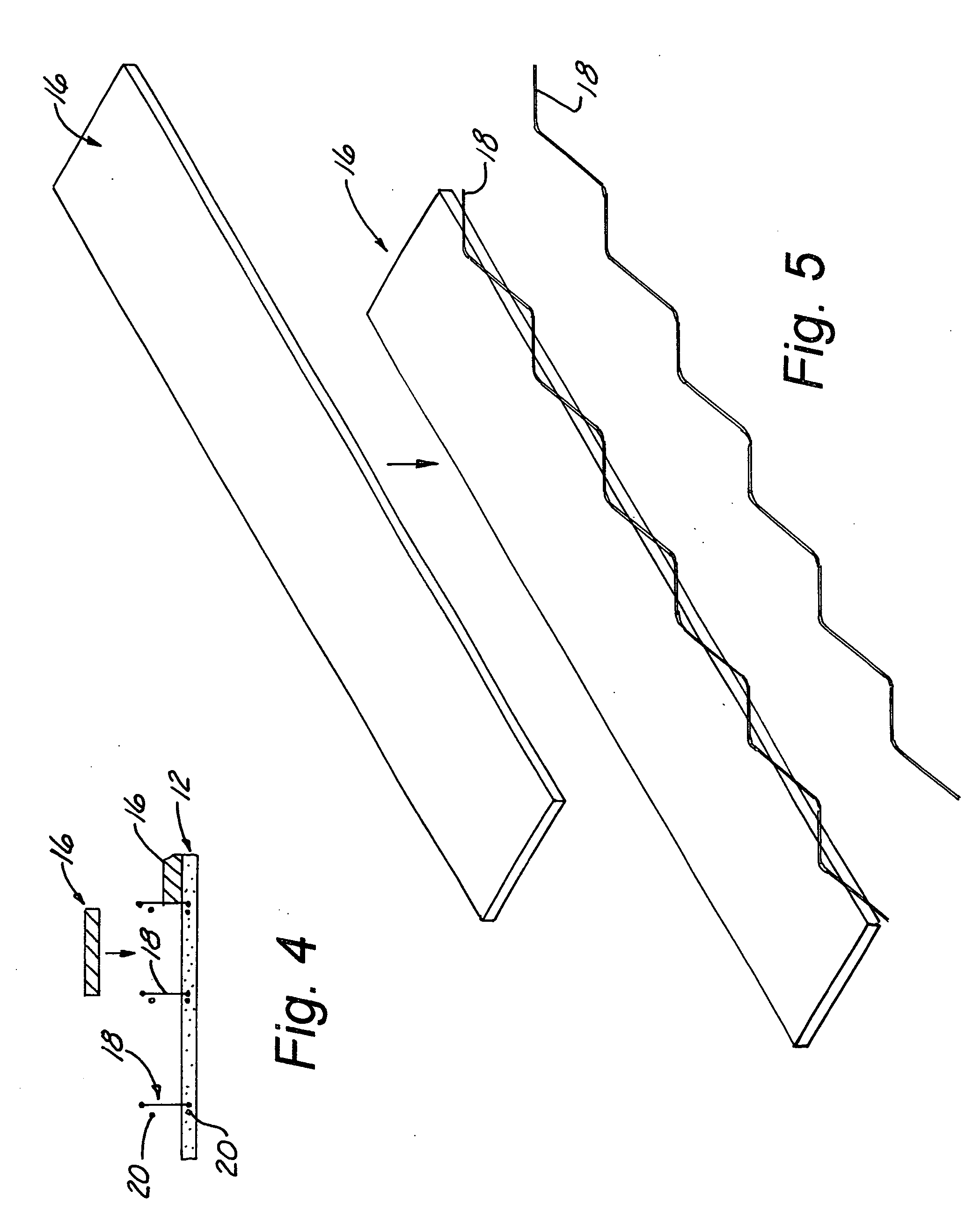
[0031] In a second embodiment, as shown in FIGS. 4-5, sinuous connecting elements 18 are attached to longitudinal reinforcing strands 20 that are located near the center of the future concrete layers. The sinuous connecting elements 18 are attached in such a manner that they extend approximately equal distances from the centerline of the future insulating layer. This attachment can be effected using wire ties or plastic clips that bind the sinuous connecting elements 18 to the longitudinal reinforcing strands 20. Multiple sinuous connecting elements 18 are installed across the width and the length of the form. A first layer of concrete 12 is placed in the form, and a relatively flexible insulating layer 16 is placed between the sinuous connecting elements 18. The second layer of concrete 14 is then placed. In this embodiment, the insulating layer 16 is flexible and resilient so as to be capable of deforming at the sinuous connecting elements 18 to form a seal around the elements and...

third embodiment

[0032] In a third embodiment, as seen in FIGS. 6-7, the order of the installation is altered. Initially, the longitudinal reinforcing strands 20 are in place in the first concrete layer 12 or both the first concrete layer 12 and the second concrete layer 14. After the first concrete layer 12 is placed in the form, flexible and resilient insulating strips 16 are installed. The sinuous connecting elements 18 are then pushed through the joints between the insulating strips 16. This may require that the form or the sinuous connecting elements 18 be vibrated during installation to allow the element to be pushed into the plastic concrete in the first layer of concrete 12. The sinuous connecting elements 18 will have depth indicators to allow the installers to gauge the depth of insertion of the elements. After insertion to the correct depth, the resilient insulating layer 16 will hold the elements at the proper depth while the second layer of concrete 14 is placed. This method is an advan...


PUM


Abstract

The present invention is an insulated concrete wall panel consisting of two layers of concrete with and insulating layer in between the concrete layers. A sinusoidal-shaped, fiber-reinforced composite element connects the two concrete layers. The connector is imbedded in the two layers of concrete and passes through the insulation layer. The connector provides the requisite transmission of forces merely by being consolidated in the concrete layers.

Description

BACKGROUND OF THE INVENTION [0001] This invention relates generally to concrete sandwich walls and, more specifically, to concrete sandwich walls wherein the two concrete layers are tied together by a sinusoidal element made of fiber-reinforced composite material. The concrete sandwich walls are both stiff and strong while providing high thermal efficiency. [0002] In a typical pre-cast concrete sandwich wall, a layer of insulation is placed between two concrete panels and the entire system is held together using some form of connecting system. Concrete sandwich wall panels are subject to lateral forces such as wind and seismic load, gravity loads, and temperature-induced forces. These lateral forces, as well as temperature differentials between the two layers of concrete induce shear forces in the connection systems as well as bending, shear, and axial forces in both layers of the panel. [0003] Concrete sandwich panels are designed as composite, partially composite, or non-composite...

Claims


Application Information

Patent Timeline
Patent Type & Authority Applications(United States)
IPC IPC(8): E04C2/04E04C2/288
CPCE04C2/044E04C2002/048E04C2/288
Inventor LONG, ROBERT T. SR.BARNETT, SCOTT OWENSEEBER, KIM E.
Owner COMPOSITE TECH CO LLC
Why Eureka
Try Eureka