Manikin and eye device apparatus, methods and articles of manufacture

a technology of eye devices and manikins, which is applied in the field of manikin and eye devices, can solve the problems of adding complications to the sculpting process, difficult eye construction and placement, and difficult construction of life-like and realistic sculptures, etc., and achieves the effect of accurate, consistent and efficient installation of artificial eyes

Inactive Publication Date: 2008-05-13
TOHICKON JOHNSON DEV
View PDF16 Cites 4 Cited by
  • Summary
  • Abstract
  • Description
  • Claims
  • Application Information

AI Technical Summary

Benefits of technology

[0016]The present invention provides apparatus, methods and articles of manufacture for accurately, consistently and efficiently installing artificial eyes or eyepiece inserts into taxidermy manikins or other life-like sculptures, such as dolls, toy animals, clothing mannequins, or other created bodies utilizing artificial eyes, thus overcoming difficulties inherent in conventional installation methods. In a preferred embodiment, a partially hemispherical eye is configured so as to permit mounting on either a manikin with eye recess or using an eye-mounting piece.
[0017]Advantageously, the present invention achieves desirable results using less glass to make modified partially hemispherical artificial eyes, thereby reducing costs. It is also quicker and easier, requiring less skill or time by the taxidermist to use the disclosed artificial eyes to create professional and realistic taxidermy mounts.
[0022]Therefore, it is an object of the present invention to provide simple, accurate apparatus and methods of artificial eye installation in realistic and life-like sculptures.

Problems solved by technology

The construction of life-like and realistic sculptures, e.g., taxidermy mounts (built upon underlying “manikin” sculptures), clothing mannequins, dolls, artistic sculptures, etc., can be extremely difficult.
One area that is especially difficult is eye construction and placement.
Each of the foregoing factors, as further described below, adds complications to the sculpting process.
However, due to mounting difficulties, hemispherical eyes do not necessarily provide a life-like installed eye on a taxidermy manikin.
Nevertheless, the material must be chosen carefully, as it may fade or crack, thereby ruining the sculpture.
If the manikin does not have designated eye locations, the taxidermist must place the eyes in an appropriate area on the face, which can be very problematic.
Also, if the eye is not located so that it appears to be looking in a life-like direction on the mounted animal, the entire completed mount will appear unnatural.
The problems are exacerbated because, of course, eyes are paired in nature, so most realistic sculptures have two eyes.
Thus, the eye placement problems are magnified because alignment and retention complications need to be considered for both of the eyes.
In a conventional mount, matching the focus of the two eyes can require hours, and require significant sculpting ability.
However, often such materials have their drawbacks.
For instance, epoxy may harden to the extent that it causes the eye to crack.
Eye mounting clay is very soft and tends to move when the skin is attached to the manikin, thus distorting the eyelids or making it very difficult to pin the skin in place around the eye.
When the skin and clay dry, they shrink; often to the extent that the eyelids move and lose shape and / or symmetry.
Additionally, the softer clay takes a considerable amount of time to dry, and as a result the entire sculpture must be set aside, thereby delaying production while waiting for the clay to dry.
Thus retaining the mounted eye in the initially desired position (e.g., forward and downward as noted above) may be very difficult.
However, by this method eyes are not consistently insert-molded into the manikin without the possibility of rotation to an incorrect orientation or displacement.
The preset eye may not be at the proper angle for a particular specimen, or may not appropriately convey a desired expression.
Moreover, the eye may shift as the foam rises and squeezes between the eye and the mold, or the method may fail to maintain the desired eye placement during curing of the foam.
Again, these devices often fail to provide proper placement for particular specimens, or they may not permit the taxidermist to appropriately convey a desired expression.

Method used


Image

  • Manikin and eye device apparatus, methods and articles of manufacture
  • Manikin and eye device apparatus, methods and articles of manufacture
  • Manikin and eye device apparatus, methods and articles of manufacture

Examples


Embodiment Construction

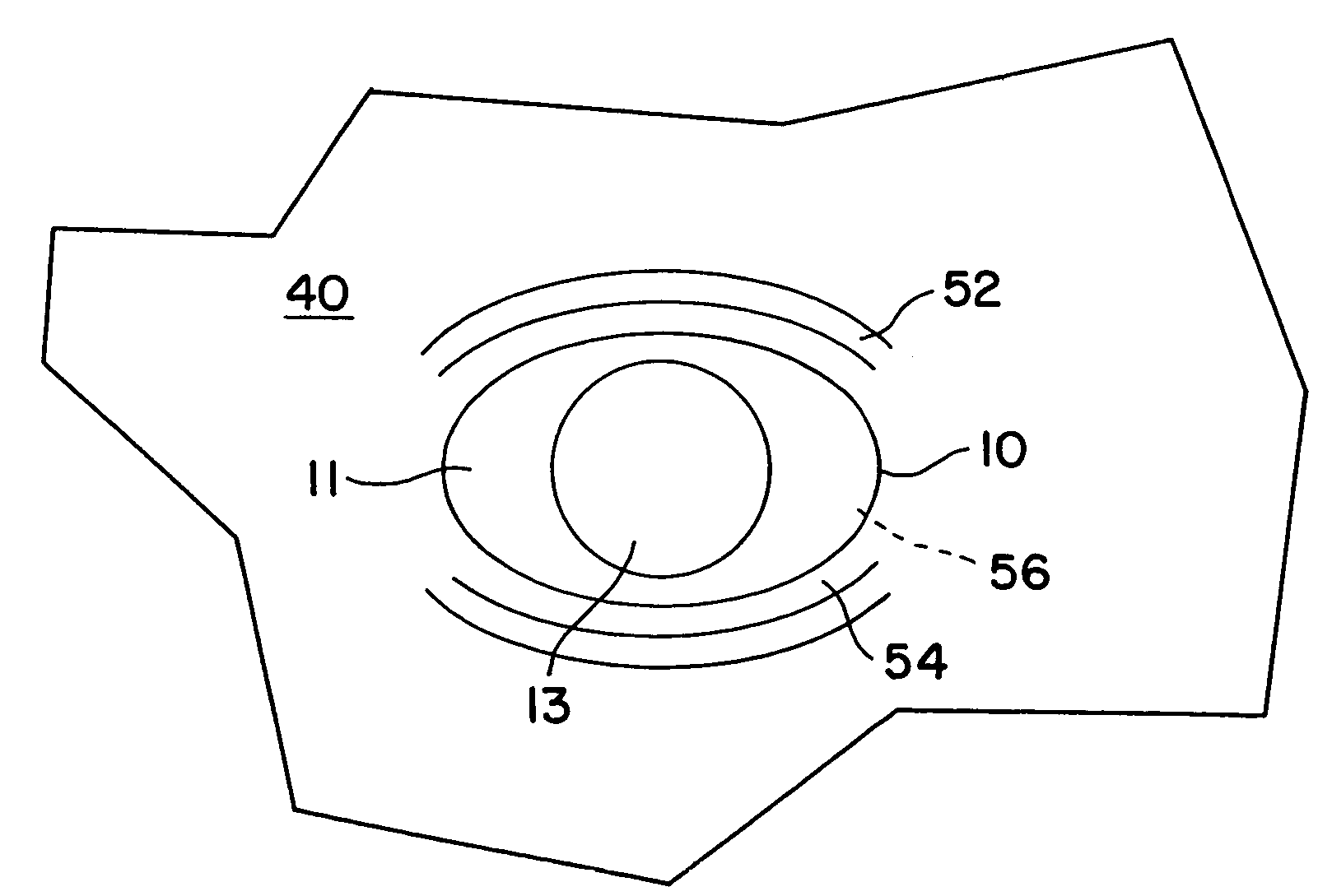
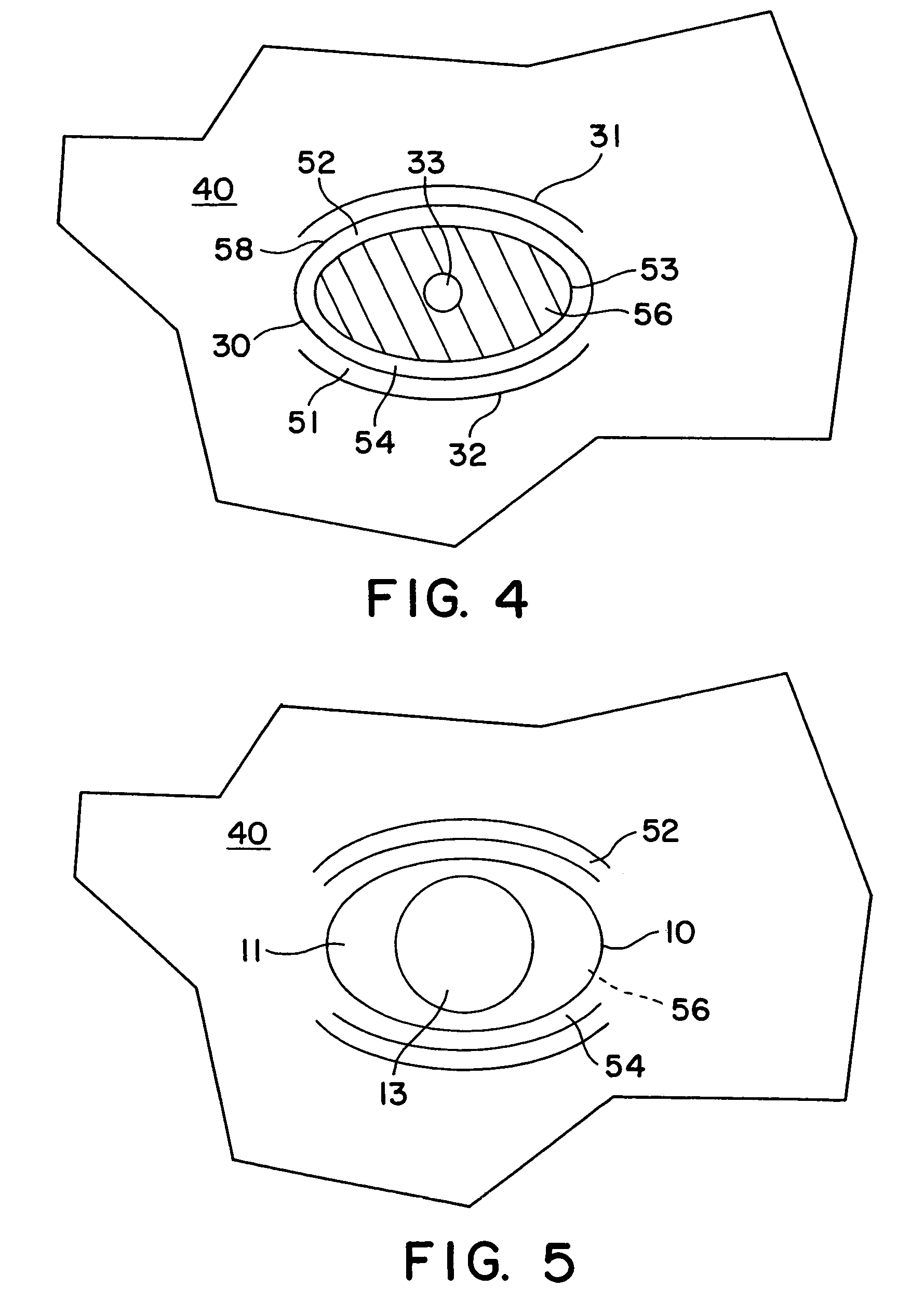
[0034]Reference is now made to the accompanying Figures for the purpose of describing, in detail, preferred embodiments of the present invention. Like elements have the same numbers throughout the several views, for example, with reference to artificial eyepiece 10, pupil 13, and eye mounting area 40 on the taxidermy manikin. The detailed description accompanying each Figure is not intended to limit the scope of the claims appended hereto.

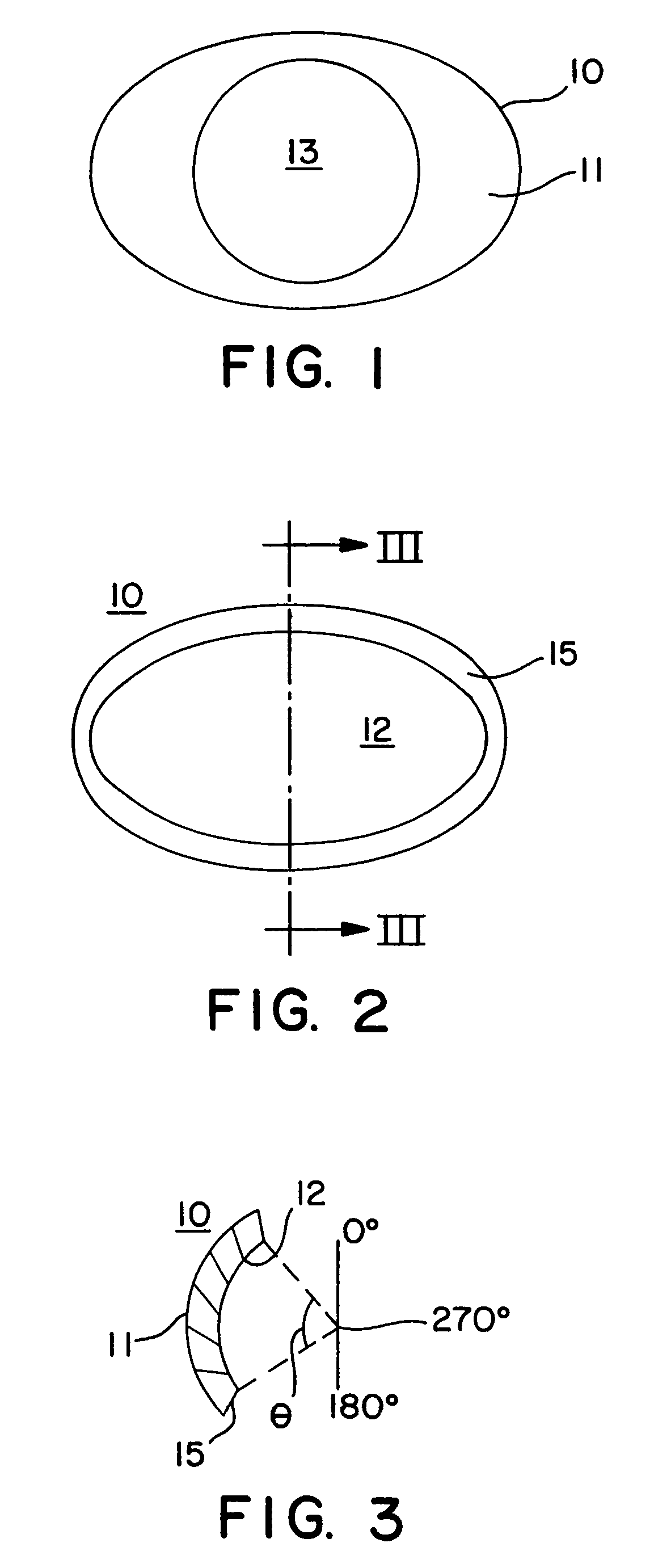
[0035]FIG. 1 depicts a preferred embodiment of an artificial eye 10. The curved front surface 11 of the eye is generally visible when installed on a manikin. The pupil 13, although present in this view, may or may not be present in any particular embodiment; that is, the user may prefer to add a pupil (and / or any other coloration) later in the process. As a result, in such an embodiment, the artificial eye would not have a pupil in its original preparation.

[0036]It should be noted that in the various embodiments of the present invention, the eye 10...


PUM

PropertyMeasurementUnit
angleaaaaaaaaaa
included angleaaaaaaaaaa

Abstract

Apparatus, methods and articles of manufacture are disclosed for installing an artificial eye in a realistic, life-like sculpture, comprising an artificial eye of partially hemispherical shape, as well as a manikin with an eye-mounting area adapted to mate with such an artificial eye without risk of subsequent movement of the eye or of distortion of the features surrounding the eye-mounting area of the sculpture. Eye mounting pieces for retrofitting existing sculptures having conventional eye mounting areas to permit the accurate and life-like mounting of artificial eyes are also provided.

Description

CROSS REFERENCE TO RELATED APPLICATIONS[0001]This application claims priority to U.S. Provisional Patent Application No. 60 / 331,316, filed Nov. 14, 2001, and U.S. patent application Ser. No. 10 / 247,063, filed on Sep. 18, 2002, now U.S. Pat. No. 6,923,654, each of which is incorporated herein in its entirety.FIELD OF THE INVENTION[0002]The present invention relates generally to apparatus, methods and articles of manufacture for sculptured bodies and artificial eyes therefor. More particularly, this invention relates to apparatus, methods and articles of manufacture for making manikins and realistically installing artificial eyes therein.BACKGROUND OF THE INVENTION[0003]The construction of life-like and realistic sculptures, e.g., taxidermy mounts (built upon underlying “manikin” sculptures), clothing mannequins, dolls, artistic sculptures, etc., can be extremely difficult. Every body part must be accurately depicted for the sculpture to be acceptable. Yet accurately depicting body pa...

Claims


Application Information

Patent Timeline
Patent Type & Authority Patents(United States)
IPC IPC(8): G09B23/00A61K47/12A61K31/557A61K31/558A61P1/10A63H3/38B29C39/44C08J5/00
CPCA61K31/557C07D311/94C07C53/23A61F2/141A63H3/38A63H3/42B29C39/18B29D11/02A61P1/10
Inventor JOHNSON, BRIAN
Owner TOHICKON JOHNSON DEV
Why Eureka
Try Eureka