

Motorcycle
a technology for motorcycles and transmissions, applied in the field of motorcycles, can solve the problems of complicated operation of switches and the peripheral of handle bars, and achieve the effect of increasing the number of shift modes without complicating the operation of transmissions
- Summary
- Abstract
- Description
- Claims
- Application Information
AI Technical Summary
Benefits of technology
Problems solved by technology
Method used
Image

Examples
Embodiment Construction
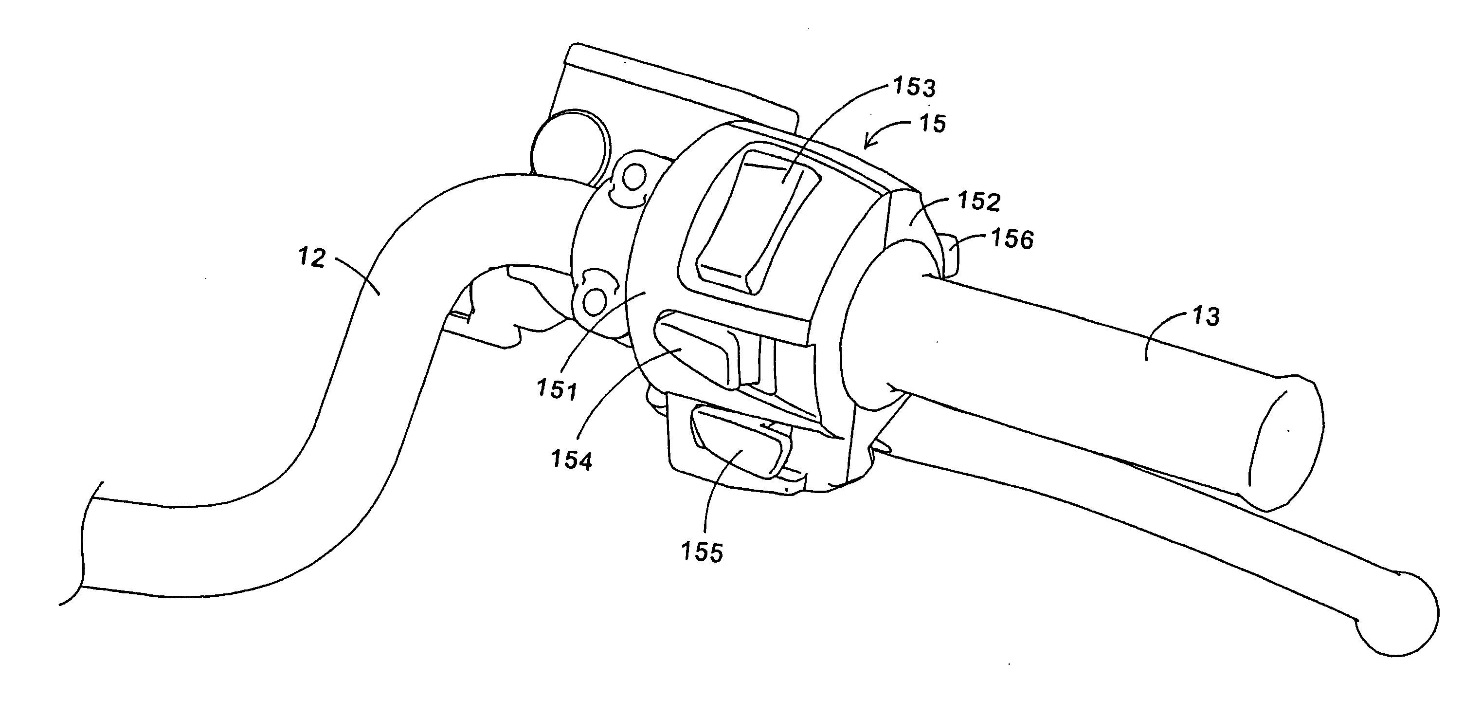
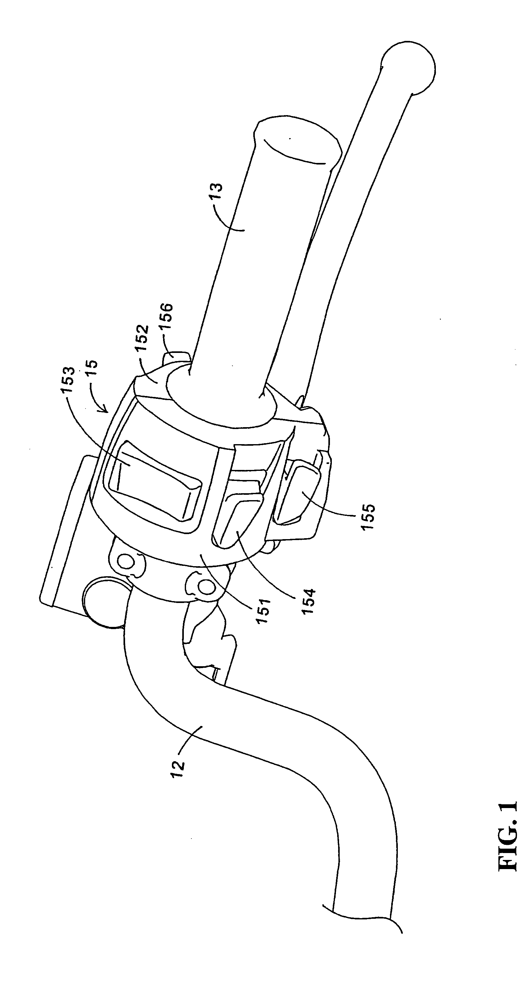
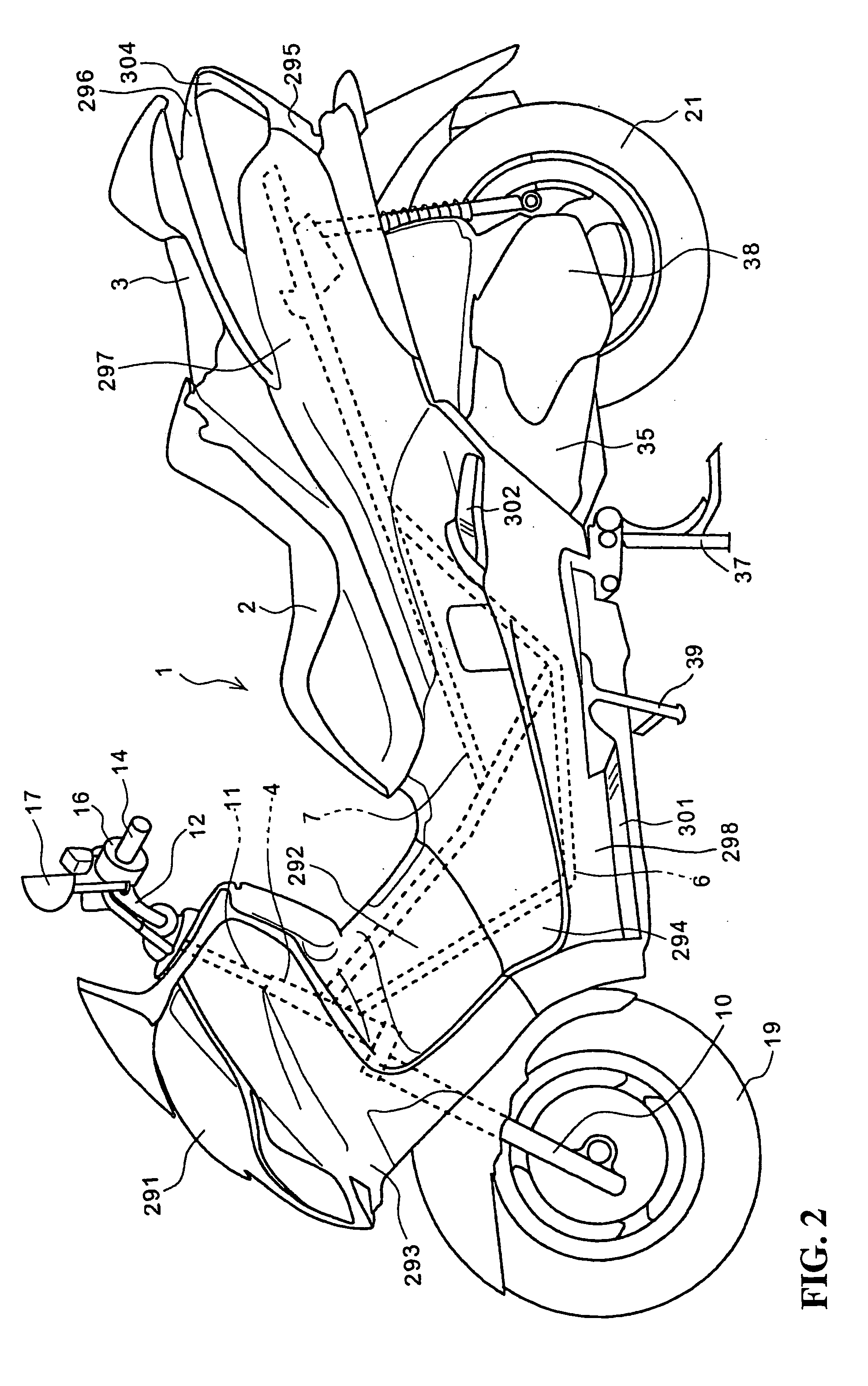
[0036] A preferred embodiment of the present invention will now be described with reference to the drawings. FIG. 2 is a side view of a motorcycle 1 according to a preferred embodiment of the present invention and FIG. 3 is a perspective view of a front portion of the vehicle as viewed from the driver's seat. As shown in FIG. 2, the motorcycle 1 is a tandem vehicle having a driver's seat 2 and a passenger's seat 3 arranged in tandem. The driver's seat 2 and the passenger's seat 3 are provided with a seat lock (not shown) adapted to be unlocked by remote control. The motorcycle 1 includes a body frame composed of a head pipe 4, a down tube 6 extending rearwardly and downwardly from the head pipe 4 and a main tube 7 extending rearwardly and upwardly from the down tube 6. A front fork 10 is rotatably supported on the head pipe 4. A handle bar 12 is mounted through a handle shaft 11 to an upper extending portion of the front fork 10. The handle bar 12 extends laterally of the vehicle bo...
PUM
 Abstract
Description
Claims
Application Information