Flow control system for a valve

a flow control system and valve technology, applied in the direction of braking systems, gas/liquid distribution and storage, vessel construction details, etc., can solve the problems of affecting the sealing effect of the valve, the valve can be subjected to extremely demanding performance expectations, and the problem of contamination may com

Active Publication Date: 2005-05-19
LUXFER CANADA
View PDF18 Cites 61 Cited by
  • Summary
  • Abstract
  • Description
  • Claims
  • Application Information

AI Technical Summary

Benefits of technology

[0009] In one embodiment of the invention, an on-off, fluid-flow control system is provided which can be manually or electrically actuated. The system comprises an inlet filter, a manual shut-off valve, a direct acting high pressure solenoid, a pneumatically operated shuttle valve, a withdrawal filter and an optional pressure sensor. The solenoid and shuttle valve act together, forming a fast-response high-flow on-off device, with opening times substantially independent of inlet and outlet conditions. Calibration of the solenoid's orifice and return spring system allows the system to prevent over-pressurizing a cylinder. Calibration of the shuttle valve component's dimensions and return spring allows the system to provide an automatic low-pressure shut-off. Use of an optional pressure sensor allows conventional system electronics to stop cylinder filling when a desired pressure is reached. The dual inlet and withdrawal filters ensure that the precision sealing system can operate in the presence of fluid contamination levels.
[0012] In another embodiment of the invention, the issue of delay from pilot flow to full flow is addressed by using a pneumatically-controlled shuttle valve to control the primary flow. A small-orifice, direct-acting solenoid controls the differential pressure across the shuttle valve. When the solenoid is opened, it causes a full input-output differential pressure to appear across the shuttle valve, opening it very quickly and is essentially independent of downstream pressure.
[0013] Further embodiments of the invention can address the sealing capability by using a piston having a spherical-nose sealing on the internal diameter of an accurately produced sealing ring as disclosed in a co-pending US application Ser. No. ______ (serial number as yet unknown) filed on or about Nov. 17, 2004 and claiming priority of U.S. Provisional application 60 / 520,680 filed Nov. 18, 2003, the entirety of which is incorporated herein by reference. The seal is nominally a ball of the spherical nose seated on a circle rather than on a lip surface. The unique sealing approach can be used for both the shuttle valve and the solenoid. With corresponding and appropriately accurate piston guidance and the use of commercial ball bearings for the sealing surfaces, very reliable systems are demonstrated.

Problems solved by technology

Valves for controlling the flow of gases can be subjected to extremely demanding performance expectations.
Challenges to such seemingly innocuous operation include contaminants which affect sealing, differential pressure across the valve which may vary widely, seal life and in the case of a valve for a gas cylinder, the avoidance of overfilling.
Problems associated with sealing are exacerbated when at high pressures and with low molecular weight gases.
In fuel gases as a typical example, contaminants may come from debris in lines at the fuel process plant; scale in the fuel distribution pipelines; debris from the installation of tubing and fittings in the application system's plumbing; and debris inside the storage cylinders left over from their original manufacture.
Currently available prior art systems do not address the issue of contaminants being present in the flow and thus are prone to erratic performance in the field.
At high supply pressures and with smaller system volumes, the delay time from pilot flow to full flow is substantially indiscernible.
However, at low supply pressures, for example less than 500 psig, the delay time becomes significant and can often reach 30 seconds or more.
Such delays are not tolerable in many applications, such as automotive applications.
As noted above, many applications for on-off solenoid valves are increasingly likely to demand leak-tight sealing across the system's entire pressure range, for example 7 to 350 bar.
Accordingly, conventional seal materials and configurations are often unable to reliably deliver the required performance.
Currently, valves with rather common plastic seats and poorly matched operators are used in practice.
The two most common types of valves have either overly large or seriously undersized operators.
The oversized operators are bulky, expensive and can easily cause seal damage with seemingly reasonable torque levels.
The undersized operators are themselves easily damaged and can have difficulty in transmitting enough torque to reliably open and close the valve.
Further, conventional valves using prior art seals made from the PTFE class of materials may be prone to seal extrusion and failure at high differential pressures.
In some gaseous fast-fill applications, achieving a proper fill level can be difficult using conventional valves and seals.

Method used


Image

  • Flow control system for a valve
  • Flow control system for a valve
  • Flow control system for a valve

Examples


Embodiment Construction

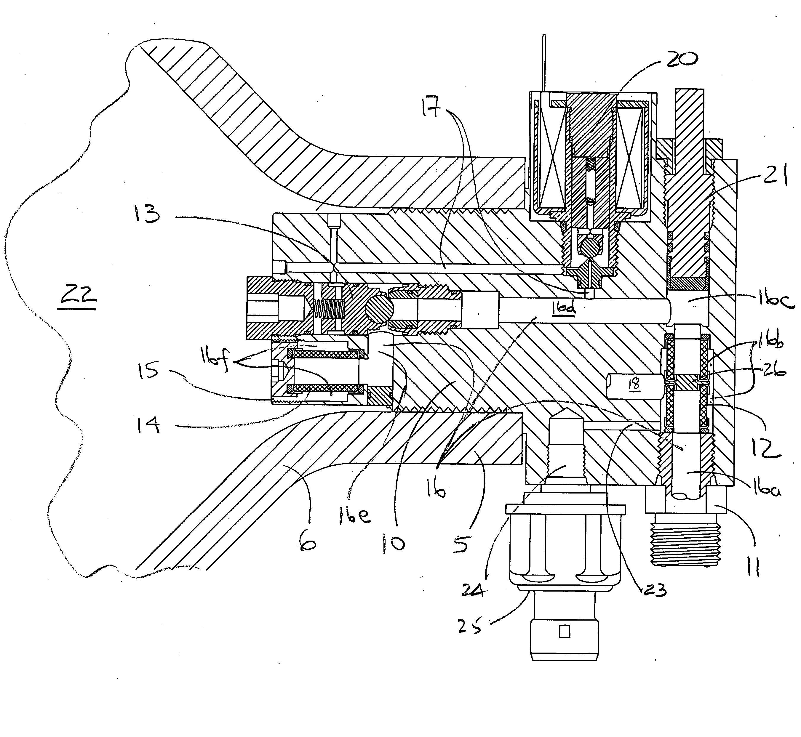
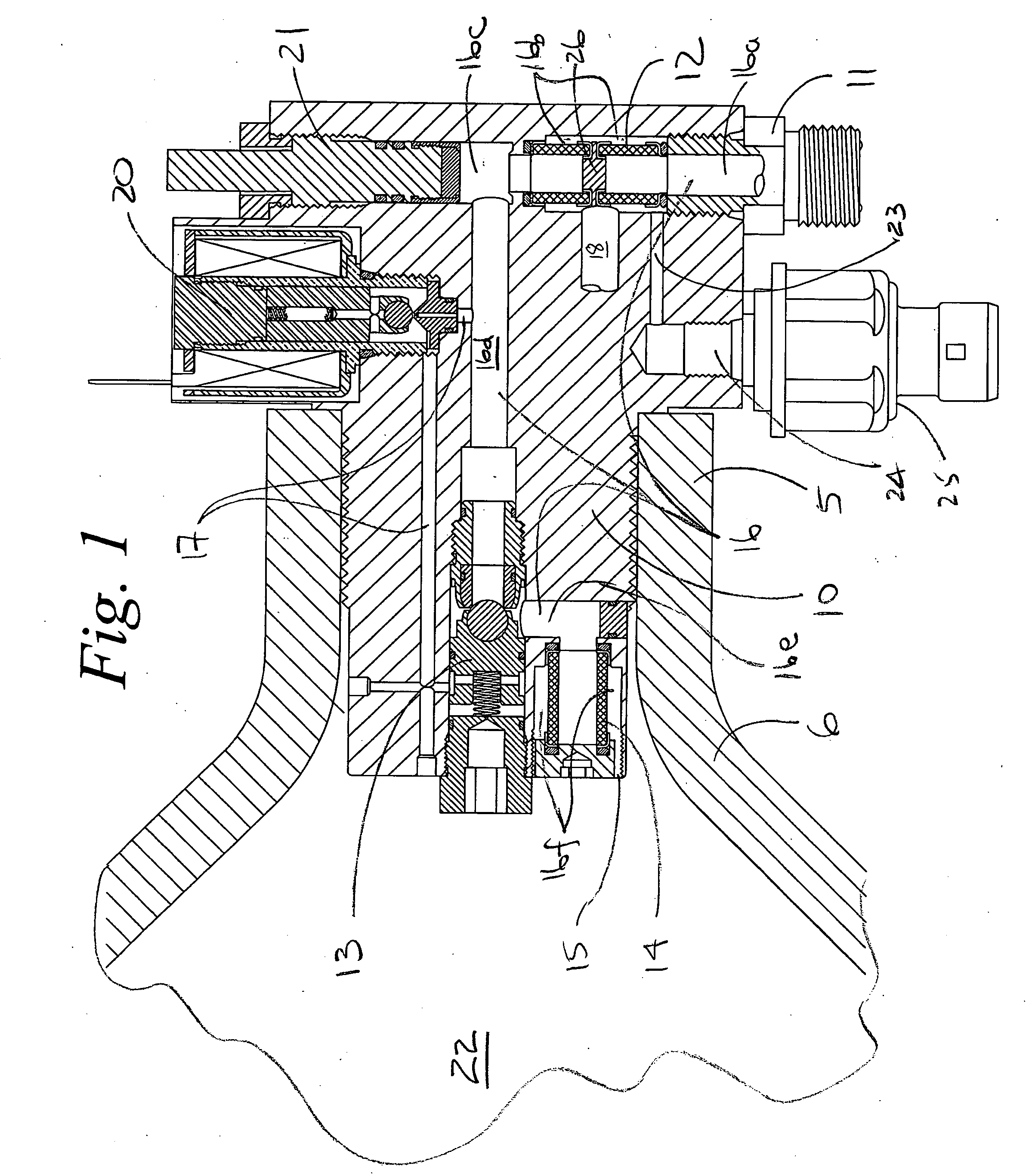
[0032] Embodiments of a flow control system for a valve are illustrated in the context of an in-cylinder control valve. Often a pressure regulator is also associated with the valve but is not illustrated in this case for a matter of some clarity. Further, the system is equally applicable to in-line remote valves which are not directly attached to the cylinder. Fluid under various pressure conditions from a first pressure area is directed bi-directionally to and from a second pressure area at various pressure conditions. In the particular embodiment shown, fluid is directed through the valve, into the cylinder (such as to fill the cylinder for storage) and withdrawn through the valve (such as for use or consumption).

[0033] With reference to FIG. 1, a flow control system is embodied in a valve body 10 installed in a structure such as the neck 5 of a high pressure cylinder 6. The valve body 10 comprises a first opening or inlet 11, an first inlet filter 12, a shuttle valve 13, and a s...


PUM


Abstract

A fluid-flow control system for a valve comprises a valve body and a bi directional main flow passage between a first and second fluid areas. The shuttle piston having a first face in direct communication with the second area and a second face in communication therewith through a bleed orifice. The second face is alternately exposed to the first fluid area through a backpressure passage and second orifice which alters the pressure differential across the shuttle piston. A second valve such as a solenoid operates to either close the second orifice wherein the shuttle piston is operable under differential pressure between the first and second pressure areas, or to close the second orifice wherein the shuttle piston is operable under differential pressure between the second pressure area and the backpressure passage. Filters at the fluid inlet and outlets protect the sealing components therein.

Description

FIELD OF THE INVENTION [0001] The invention relates to the control of bi-directional flow through a valve under high and low pressure and flow conditions. More particularly, a valve is provided for controlling filling and discharging gas from a cylinder. BACKGROUND OF THE INVENTION [0002] Valves for controlling the flow of gases can be subjected to extremely demanding performance expectations. In particular, on-off solenoid valves are expected to provide leak-tight sealing when closed and to respond quickly when between on and off. Challenges to such seemingly innocuous operation include contaminants which affect sealing, differential pressure across the valve which may vary widely, seal life and in the case of a valve for a gas cylinder, the avoidance of overfilling. Problems associated with sealing are exacerbated when at high pressures and with low molecular weight gases. [0003] In more detail, while flow-limiting orifices in such systems can be 0.250″ (6.35 mm) in diameter and l...

Claims


Application Information

Patent Timeline
Patent Type & Authority Applications(United States)
IPC IPC(8): F16K31/06F16K31/40F16K39/02F17C13/04
CPCF16K31/406F17C13/04F17C2205/0326F17C2205/0329F17C2205/0385F17C2221/012Y02E60/321F17C2223/036F17C2250/043F17C2250/0636F17C2260/021F17C2260/036F17C2270/05F17C2223/0123Y02E60/32Y10T137/7761Y10T137/7793
Inventor CARTER, STEPHEN A.
Owner LUXFER CANADA
Why Eureka
Try Eureka