Vapor compression system for heating and cooling of vehicles

a technology of vapor compression system and vehicle, which is applied in the direction of heating types, lighting and heating apparatus, instruments, etc., can solve the problems of large exhaust/refrigerant heat exchanger size, corrosion problems that may occur on the exhaust, and oil decomposition in the exhaust gas heat recovery heat exchanger, so as to reduce the heat load and accelerate the engine heating

Inactive Publication Date: 2005-05-19
SINVENT AS
View PDF4 Cites 62 Cited by
  • Summary
  • Abstract
  • Description
  • Claims
  • Application Information

AI Technical Summary

Benefits of technology

[0007] The system can supply heat to the engine coolant circuit through the auxiliary heat exchanger for more rapid engine heating and to reduce the heat load on the exterior heat exchanger when the system is operated in cooling mode. When operating in heat pump mode the system can use the coolant system fully or partially as a heat source. The reversing process from heat pump to cooling mode operation, and vice versa, can be performed by means of a flow reversing device and two multi-function expansion devices.

Problems solved by technology

The disadvantage of this system is the possibility of oil decomposition in the exhaust gas heat recovery heat exchanger (when not in use) as the temperature of the exhaust gas is relatively high.
Another disadvantage is the corrosion problems that may occur on the exhaust-side in the heat recovery heat exchanger.
A third disadvantage is the considerable size of the exhaust / refrigerant heat exchanger, and its vulnerable position under the vehicle.
A fourth disadvantage of this system is that the pressure in the high side of the circuit cannot be controlled when the circuit is operated in heat pump mode.
This may give operational problems such as insufficient capacity and low efficiency.
Finally, a fifth disadvantage of this system is the absence of an internal heat exchanger in the circuit.
Without this heat exchanger, the system will not achieve maximum capacity and efficiency in cooling-mode operation at high ambient temperature.
The disadvantage of this system is that it can only absorb heat from the engine coolant circuit, and at start-up, this may delay the heating-up time of the engine coolant and the engine itself.
Consequently, the engine needs more time to reach normal temperature, with increased pollutant emission and fuel consumption as a likely result.
In addition, the system may have to operate with extremely low evaporating temperature at start-up.
Another disadvantage with this system is the inability to provide dehumidification of the passenger compartment air in heat pump mode, which may give reduced windshield defogging or defrosting effect compared to a system with dehumidification options.

Method used


Image

  • Vapor compression system for heating and cooling of vehicles
  • Vapor compression system for heating and cooling of vehicles
  • Vapor compression system for heating and cooling of vehicles

Examples


first embodiment

1. FIRST EMBODIMENT

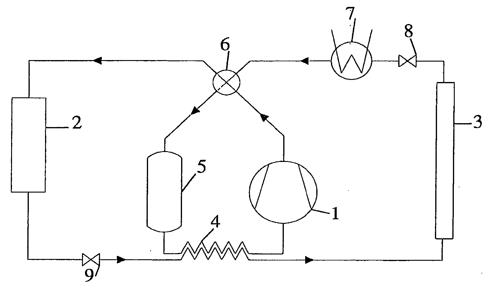
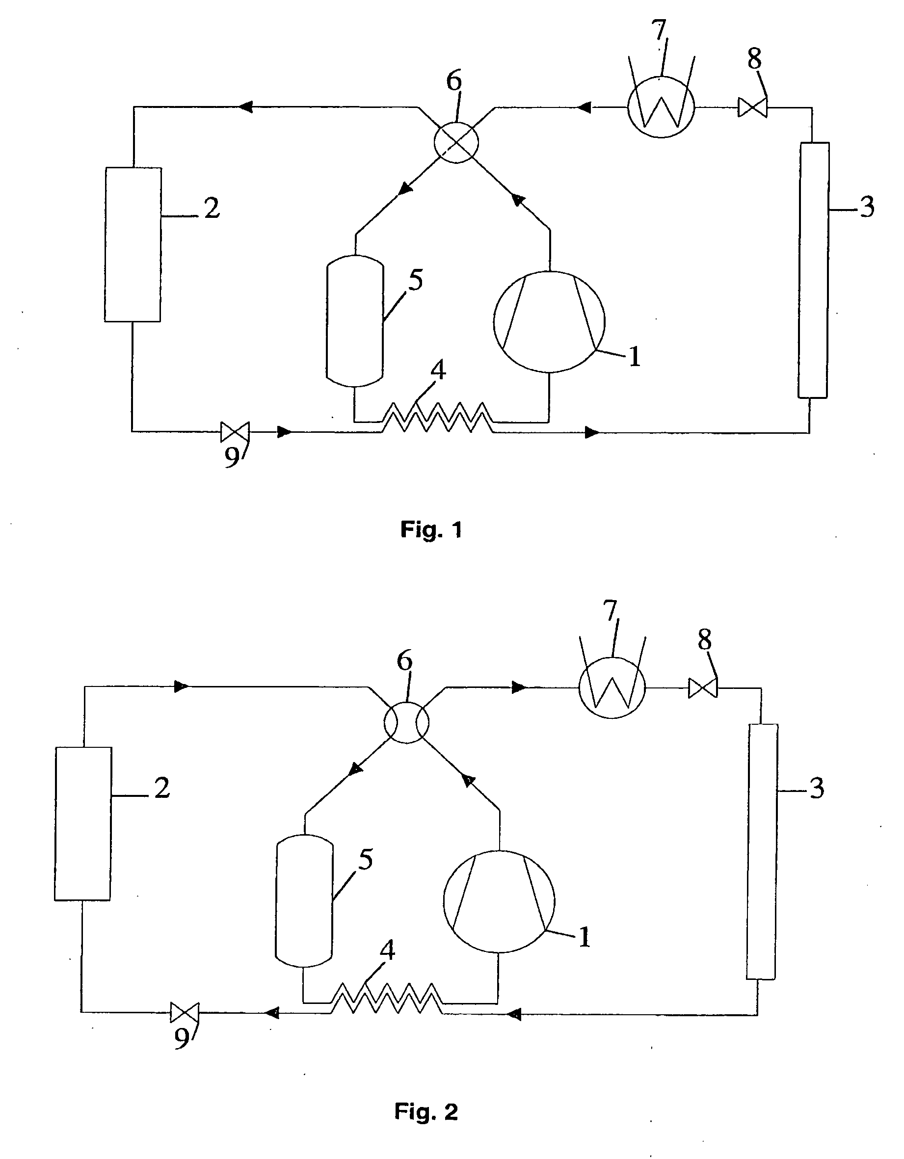
[0047] The First embodiment of the present invention for a reversible vapor compression cycle is shown schematically in FIG. 1 in heat pump mode and FIG. 2 for comfort cooling operation. In accordance with the present invention, the device includes a compressor 1, a flow-reversing device 6, an interior heat exchanger 2, a multi-function expansion device 9, an internal heat exchanger 4, an exterior heat exchanger 3, another multi-function expansion device 8, an auxiliary heat exchanger 7 and an accumulator 5. The system operation in heat pump and cooling mode is described with reference to FIG. 1 and FIG. 2 respectively.

Heat Pump Operation (FIG. 1):

[0048] When the system is running as heat pump, the compressed refrigerant after the compressor flows first through a flow-reversing device 6 that is in heating mode. The refrigerant then enters the interior heat exchanger 2, giving off heat to the heat sink (cabin / passenger compartment air, or secondary fluid) before...

second embodiment

2. SECOND EMBODIMENT

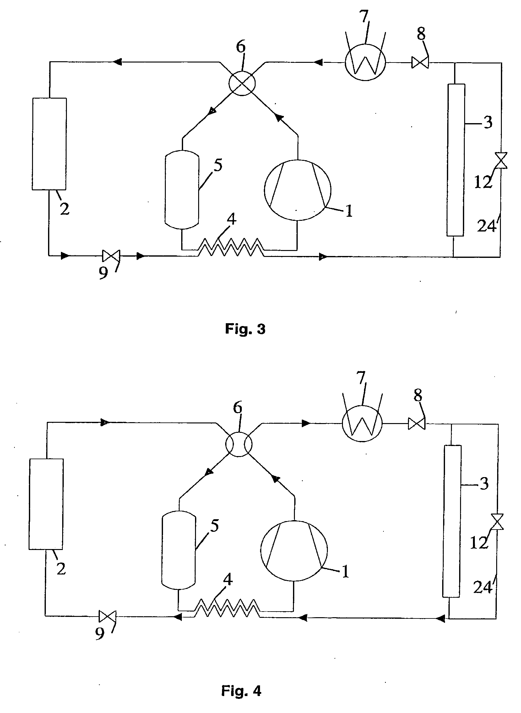
[0050] The second embodiment is shown schematically in FIG. 3 and FIG. 4 in heat pump and cooling mode respectively. The main difference between this embodiment and the First embodiment is the presence of a bypass conduit 24 providing a valve 12 which add the option to bypass the exterior heat exchanger 3 if needed.

third embodiment

3. THIRD EMBODIMENT

[0051]FIG. 5 and FIG. 6 show schematic representation of this embodiment in heat pump and cooling mode operation respectively. Compared to the First embodiment, it has an additional conduit and flow-diverting device 19 for bypassing the internal heat exchanger 4. It is also possible to provide a bypass conduit 25 in order to bypass the exterior heat exchanger 3 as in the Second embodiment. Under very low ambient (heat source) temperature (low evaporation temperature), it might be desirable to avoid too high discharge temperature. In such cases, the refrigerant after the multi-function expansion device 9 is totally or partially diverted by the flow-diverting device 19 in order to bypass the internal heat exchanger 4. The reversing process from heating mode to cooling mode operation is performed by using the two multi-function expansion devices 8 and 9 as described in the First embodiment.


PUM


Abstract

Reversible vapor compression system including a compressor (1), an interior heat exchanger (2), an expansion device (6) and an exterior heat exchanger (3) connected by means of conduits in an operable relationship to form an integral main circuit. A first means is provided in the main circuit between the compressor and the interior heat exchanger, and a second means is provided on the opposite side of the main circuit between the interior and exterior heat exchangers to enable reversing of the system from cooling mode to heat pump mode and vice versa.

Description

FIELD OF THE INVENTION [0001] The present invention relates to reversible vapor compression system for heating and comfort cooling of a vehicle cabin or passenger compartment, including at least a compressor, a flow reversing device, an interior heat exchanger, a multi-function expansion device, an internal heat exchanger, an exterior heat exchanger, another multi-function expansion device, an auxiliary heat exchanger through which a coolant is circulated and an accumulator connected in an operational relationship to form a closed main circuit. The system is operating under trans-critical or sub-critical conditions using any refrigerant and in particular carbon dioxide. More specifically the system is related to reversible refrigeration / heat pump systems for vehicles operating with electrical, internal combustion or hybrid drive systems. DESCRIPTION OF PRIOR ART [0002] In reversible vapor compression systems for mobile applications, it is desirable to use waste heat from the drive s...

Claims


Application Information

Patent Timeline
Patent Type & Authority Applications(United States)
IPC IPC(8): B60H1/00F25B1/00F25B1/10F25B9/00F25B13/00B60H1/32F25B27/02F25B40/00
CPCB60H1/00907B60H2001/00935B60H2001/00949B60H2001/00957F25B1/10F25B9/008F25B2600/2501F25B40/00F25B2309/061F25B2313/021F25B2313/02341F25B2313/02343F25B2400/13F25B13/00B60H1/00B60H1/32
Inventor AFLEKT, KAREJAKOBSEN, ARNEPETTERSEN, JOSTEINSKAUGEN, GEIRHAFNER, ARMINNEKSA, PETTERREKSTAD, HAVARDZAKERI, GHOLAM REZA
Owner SINVENT AS
Why Eureka
Try Eureka