Wire feed speed and current adjustable welding torch with remote selection of parameters

a technology of wire feed speed and current, which is applied in the field of tig and mig welding apparatus, can solve the problems of inability to remotely locate more than the welding torch head, the tig welding tools do not provide an automatic or integrated application of welding wire, and the effect of increasing or decreasing the speed of material delivery

Inactive Publication Date: 2005-05-19
WARD JOSEPH J
View PDF4 Cites 50 Cited by
  • Summary
  • Abstract
  • Description
  • Claims
  • Application Information

AI Technical Summary

Benefits of technology

[0013] Accordingly, it is the object of the present invention to provide a TIG or MIG welding apparatus control wherein the user can selectively control, through a singular control mechanism, either the wire feeding speed, or the current used, or both in the process of welding while the non-selected parameter remains at a preselected value.
[0014] It is also the object of the present invention to provide a means to freely adjust the delivery speed of the welding wire or material simultaneously while conducting a welding operation with either a TIG or a MIG style welding torch by providing such control to the welding torch operator at the location of the operator and in a manner which frees the operator from the need to use a separate hand to control the selected parameters.
[0015] It is another object of the present invention to provide a means and apparatus to provide the welding torch operator with the ability to select the control of wire speed and current used in the welding process simultaneously over a preselected range through the use of one control attached the a welding torch with a trigger like configuration or a separate foot petal which controls the selected parameters simultaneously over a preselected range throughout the range of travel of the control device.
[0016] It is yet another object of the present invention to provide a means to adjust either the delivery rate of the welding wire or the welding current in a TIG or MIG welding apparatus by manipulation of a user control which is available to the user without discontinuing the welding operation or releasing the welding head handle.
[0017] It is a further object of the present invention to provide a means to adjust the speed of the welding wire material delivery and the current used in the welding process simultaneously while conducting the welding operation.

Problems solved by technology

While such apparatus does provide for an automatic wire feed through the center gas cup of the torch, the apparatus is not portable, the welding torch head cannot be remotely located more than perhaps twenty-five feet from the welding machine or apparatus, and the MIG system provides other disadvantages.
Present TIG welding tools do not provide for an automatic or integrated application of welding wire to an existing TIG torch and torch handle, or for adjustability of the speed of the wire being fed to the head of the torch.
Present equipment available today, which provides for automatic wire feed in a TIG torch operation, usually requires more than one operator, who must be specially trained, to operate large, expensive welding systems that cannot be adapted to any standard TIG torch or welding machine.
As is evident from the disclosure in Imaizumi, the welding wire feed mechanism is not adapted to be used with existing, conventional TIG touch handles.
None of the equipment found in the existing art provides for a simple, portable means to automatically deliver wire to any standard TIG torch where the operator can continually adjust, regulate or otherwise control the feed speed of the wire being used in the welding process.
The existing art does not provide for a simple means to adapt a TIG welding torch with a welding wire feed mechanism which is also capable of wire feed speed control and does not require altering or permanently modifying the existing torch to allow operation.
Since such apparatus is typically located in a position remote from the welding job and the location of the actual torch and operator, it is not convenient to adjust the current controls or wire feed speed.

Method used


Image

  • Wire feed speed and current adjustable welding torch with remote selection of parameters
  • Wire feed speed and current adjustable welding torch with remote selection of parameters
  • Wire feed speed and current adjustable welding torch with remote selection of parameters

Examples


Embodiment Construction

[0022] And now the invention will be described in detail, with reference to the various figures in which like numerals refer to like parts.

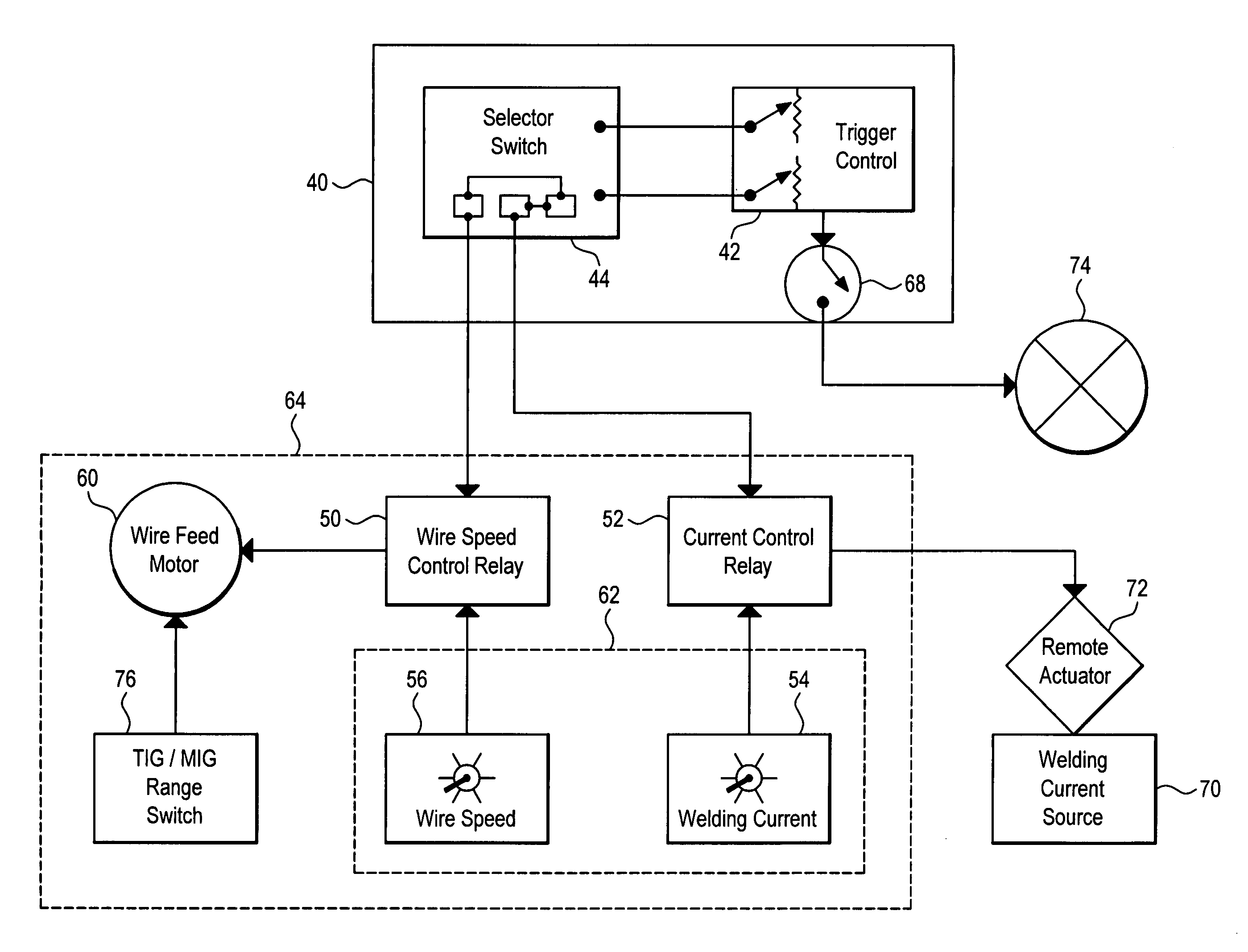
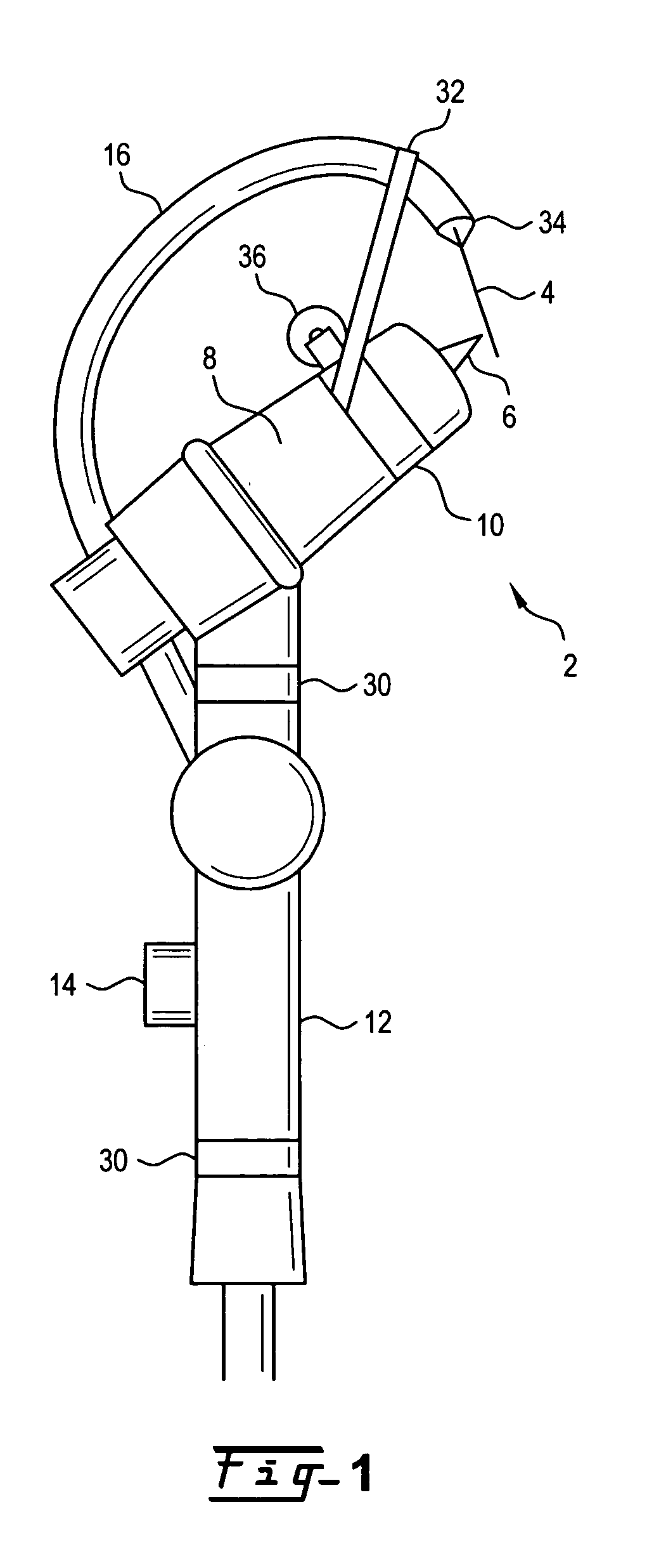
[0023] Turning now to FIG. 1, a TIG Welding Torch 2 is shown in a conventional configuration, along with a wire feed device attached. Feed wire 4 is delivered through wire feed tube 16 to close proximity of arc tip 6 where an electrical arc causing the welding process initiates. Hyperbaric TIG Welding, also known as Gas Tungsten Arc Welding is widely used as a technique for making the root pass and some subsequent passes in manual hyperbaric welding procedures.

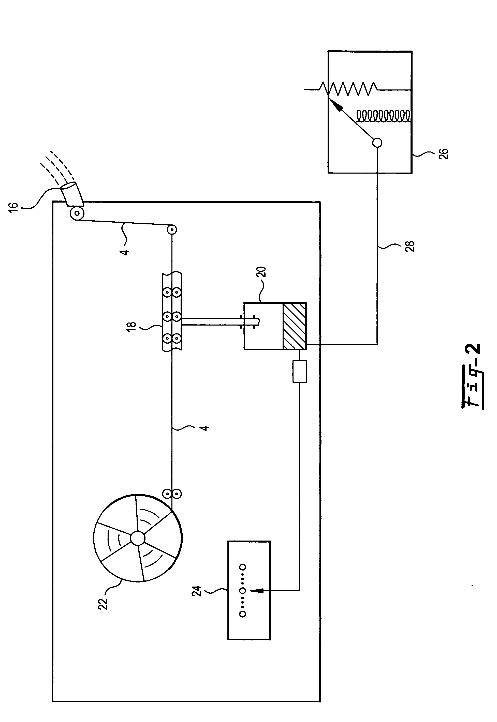
[0024] An automatic feed welding torch, sometimes commonly known as a MIG which provides for the automatic feed of feed wire through the center of the gas cup and the wire being fed is used as the arc electrode. The wire in a MIG welder is consumed in the welding process. A MIG welder has a preselected delivery rate of the wire to the joint to be welded. In both MIG and TIG welders, a str...


PUM

PropertyMeasurementUnit
sizeaaaaaaaaaa
speedaaaaaaaaaa
currentaaaaaaaaaa

Abstract

An arc welding torch control system providing remotely selectable control over welding wire feed rate and welding current without discontinuing use of the welding device. A torch mounted three position switch provides for selection of variable wire feed rate with constant preselected current control, variable current control with a preselected constant wire feed rate, or simultaneous variation of both parameters over a given preselected range. Control of the selection and parameter range control is remotely presented to the welding operator by use Of torch mounted controls or by remote controls co-located in the immediate location of with the welding torch so that the operator can manipulate the rate of the selected parameter by foot or otherwise without the need to discontinue the welding operation.

Description

CROSS REFERENCES TO RELATED APPLICATIONS [0001] This application is a continuation-in-part of the applicant's pending application Ser. No. 10 / 263,034 filed Oct. 2, 2002, which claims the benefit of the applicant's provisional application Ser. No. 60 / 326,542 which was filed Oct. 2, 2001.BACKGROUND OF THE INVENTION [0002] 1. Field of the Invention [0003] The present invention relates to arc welding apparatus, and more particularly to TIG and to MIG welding apparatus wherein welding wire feeding speed and welding current may be selectably adjusted and controlled through a single point of activation such as a trigger attached to the welding torch handle. The present invention also provides a means for a welding torch operator to control the current, wire feeding speed, or both selectively from a location remote from the main current control and wire speed control through a single point of control by selecting the preferred variable parameter from a control on the welding torch. [0004] 2...

Claims


Application Information

Patent Timeline
Patent Type & Authority Applications(United States)
IPC IPC(8): B23K9/10B23K9/12B23K9/167
CPCB23K9/10B23K9/167B23K9/124B23K9/122
Inventor WARD, JOSEPH J.
Owner WARD JOSEPH J
Why Eureka
Try Eureka