
Particle beam apparatus

a beam apparatus and beam technology, applied in the direction of material analysis using wave/particle radiation, instruments, nuclear engineering, etc., can solve the problems of deterioration of vacuum, significant shrinkage of thermal conductors, and contamination of vacuum, and achieve the effects of less thermal conductivity resistance, high thermal conductivity, and low linear coefficient of thermal expansion of carbon fibers

Active Publication Date: 2005-05-19
CARL ZEISS SMT GMBH
View PDF10 Cites 9 Cited by
  • Summary
  • Abstract
  • Description
  • Claims
  • Application Information

AI Technical Summary

Benefits of technology

[0007] It is an object of the invention to provide a particle beam apparatus which avoids the disadvantages connected with the state of the art. It is another object of the invention to significantly increase the thermal conductivity between the anti-contaminator and / or the specimen holder on the one hand and the cooler on the other hand. A further object of the invention is to reduce the shrinkage of the thermal conductor during the cooling down thereof and to reduce the expansion of the thermal conductor associated with the heating thereof.
[0010] With the use of carbon fibers as thermal conductors, a thermal conductivity, which is higher by approximately a factor of 3, is achieved compared to the use of copper as a thermal conductor. In this way, the thermal conductivity resistance is less by a factor of 3 with conditions otherwise the same compared to the use of copper rods as a thermal conductor. For this reason, a lower temperature can be reached at the cooling location, the cooling surfaces and / or the specimen holder. At the same time, the linear coefficient of thermal expansion of carbon fibers is very low compared to the linear coefficient of thermal expansion of copper. In this way, and with a suitable matching to the connecting geometry, a total expansion performance of approximately 0 can be achieved.

Problems solved by technology

In electron microscopes, especially transmission electron microscopes, wherein a good vacuum is required in the region of the specimen which is to be microscoped, the problem occurs that substances, which outgas from the specimen, deteriorate the vacuum, that is, the vacuum becomes contaminated.
Copper has a high linear coefficient of expansion and therefore considerable shrinkages of the thermal conductor occur when there is a cooling to the temperature of the cooler, which, as a rule, is liquid nitrogen.
This is always connected with cooling losses which reduce the efficiency of the cooling.
This resistance limits the minimum temperature which can be realized at the anti-contaminator and therefore the capacity thereof.

Method used


Image

  • Particle beam apparatus
  • Particle beam apparatus
  • Particle beam apparatus

Examples


Embodiment Construction

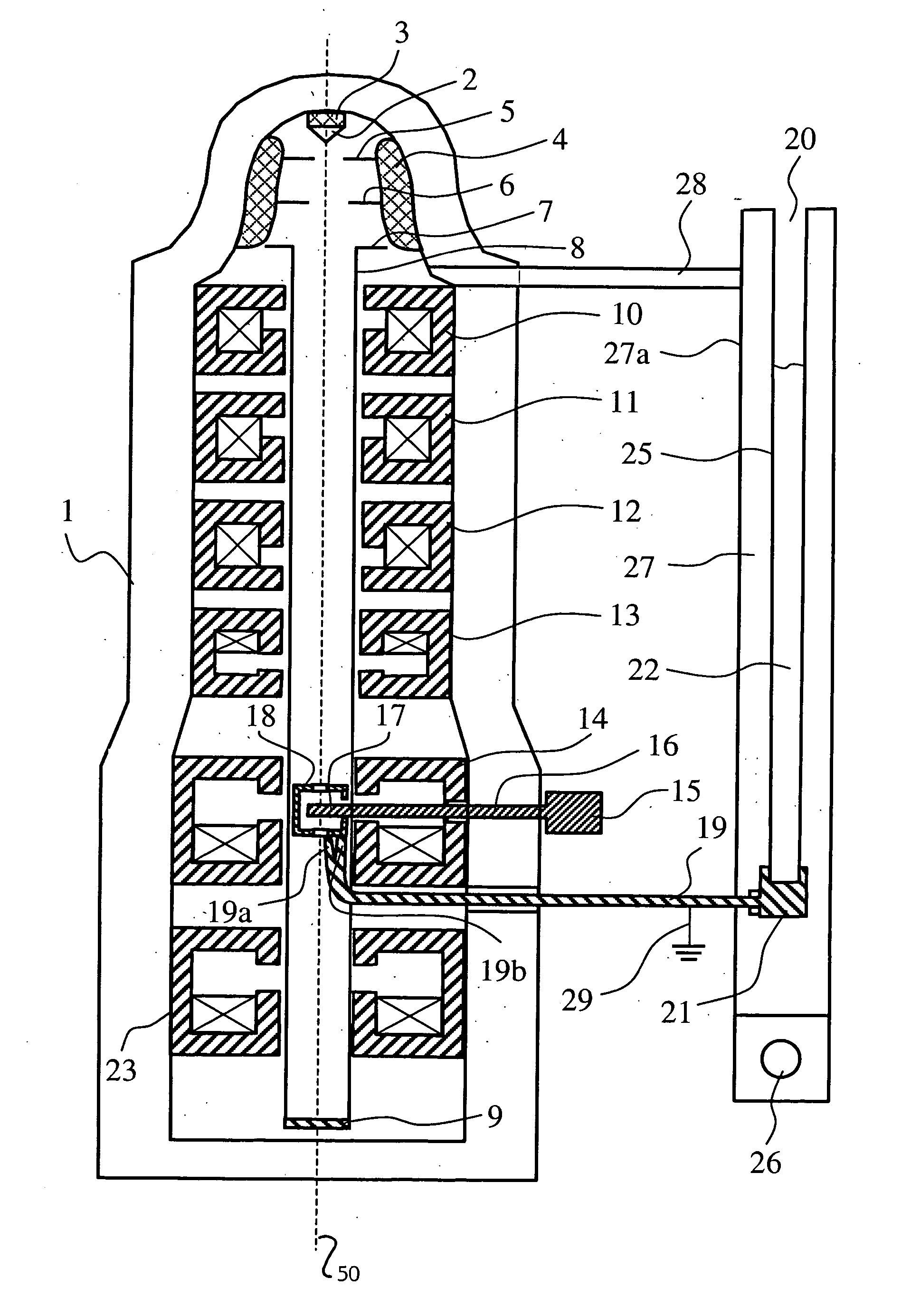
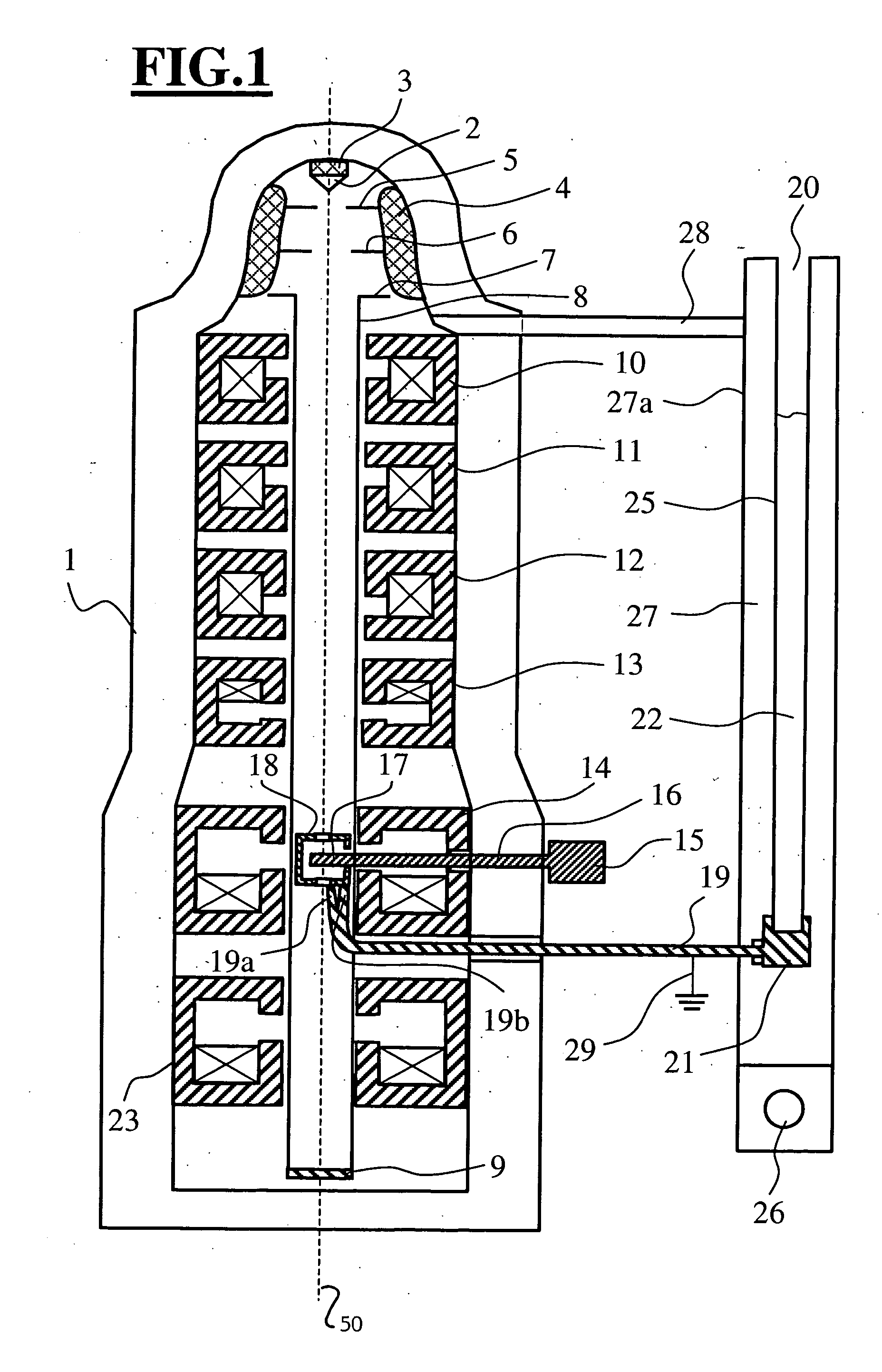
[0016] The particle beam apparatus in FIG. 1 includes a vacuum column 1 wherein the electron-optical components are mounted. In this embodiment, the electron-optical components include especially an electron source 2 which is accommodated on an insulator 3 within the vacuum column. Several accelerator electrodes (5, 6, 7) are mounted on a further insulator 4 within the vacuum column. The accelerator electrodes (5, 6, 7) are at a positive potential relative to the electron source 2. The electrode 7 is the farthest away from the electron source 2 and forms the anode which defines the end energy of the electron beam. The anode 7 is at a potential of 100 to 200 kV (if required, also 300 kV) higher relative to the electron source 2 and simultaneously lies at the potential of the vacuum column, that is, as a rule, at ground potential. The anode 7 is connected to a beam guide tube 8 which is electrically conducting. The beam guide tube 8 extends through the entire particle beam apparatus u...


PUM


Abstract

A particle beam apparatus has a cooled anti-contaminator (18) and / or a cooled specimen holder (17). A thermal conductor (19) is provided for providing a connection between the anti-contaminator (18) and / or the specimen holder (17), on the one hand, and the cooler (21) of a cryogen vessel (20) on the other hand. The thermal conductor (19) includes a carbon fiber bundle. With the carbon fiber bundle (19), a high thermal conductivity is ensured between the cooler (21) and the surfaces (17, 18) to be cooled. At the same time, thermal expansions are avoided which lead to a displacement of the anti-contaminator (18) and / or the specimen holder (17).

Description

CROSS REFERENCE TO RELATED APPLICATION [0001] This application claims priority of German patent application no. 103 44 492.0, filed Sep. 24, 2003, the entire content of which is incorporated herein by reference. FIELD OF THE INVENTION [0002] The invention relates to a particle beam apparatus having a beam of charged particles, especially, particle beam apparatus such as transmission electron microscopes and raster electron microscopes. More specifically, the invention relates to particle beam apparatus of this kind with cooled components in proximity of a specimen to be accommodated. BACKGROUND OF THE INVENTION [0003] In electron microscopes, especially transmission electron microscopes, wherein a good vacuum is required in the region of the specimen which is to be microscoped, the problem occurs that substances, which outgas from the specimen, deteriorate the vacuum, that is, the vacuum becomes contaminated. In order to avoid such a contamination of the vacuum, so-called anti-conta...

Claims


Application Information

Patent Timeline
IPC IPC(8): G01N23/00H01J37/20H01J7/24H01J37/02H01J37/09H01J37/26
CPCH01J37/20H01J37/26H01J2237/002H01J2237/2802H01J2237/2001H01J2237/28H01J2237/182
Inventor MULLER, HELMUT
Owner CARL ZEISS SMT GMBH
Learn More