Highly constrained tomography for automated inspection of area arrays

a tomography and automated inspection technology, applied in the direction of material analysis using wave/particle radiation, instruments, nuclear engineering, etc., can solve the problems of difficult or impossible to distinguish good joints from bad joints in transmission radiographs, preventing easy interpretation, and affecting the accuracy of the imag

Inactive Publication Date: 2005-05-19
AGILENT TECH INC
View PDF7 Cites 102 Cited by
  • Summary
  • Abstract
  • Description
  • Claims
  • Application Information

AI Technical Summary

Benefits of technology

[0023] The estimated model MEST, posterior probability distribution, and/or calculated expectations may then be used to automatically classify the imaged

Problems solved by technology

In manufacturing electronic assemblies, for example, solder joints or other interconnects are often not accessible for electrical testing or optical inspection.
First, modern printed circuit assemblies (PCAs) are typically double-sided, and, in addition, may possess multiple internal layers.
As a result, joints or components frequently obscure other joints in transmission radiographs, preventing easy interpretation.
Second, many joint types are themselves 3-dimensional in nature, making it difficult or impossible to distinguish good joints from bad joints in transmission radiographs.
Unfortunately, such conventional methods typically perform poorly when applied to arrays of 3-dimensional solder joints, leading to sever artifacts in the reconstructed images that impede interpretation and automatic classification.
Among the cause of such artifacts are poor signal to noise ratio (SNR), limited projection angles, lack of linearity, and X-ray scattering.
Additionally, angles at which projection data may be collected are severely limited by nearby joints which are similarly highly attenuating.
Equatorial projections are not available, for example, since each ray would typically pass through a large number of joints.
Axial projections with acceptable SNR may also be difficult or impossible to obtain at reasonable doses (e.g., for CGAs or similar joints which are longest in the axial direction).
When projections from a limited range of angles are available, or are corrupted by noise, exact reconstruction is not possible in the absence of additional information.
High attenuation combined with the use of a polychromatic source also leads to difficulties with reconstruction.
This poses two closely related difficulties for standard methods of tomographic reconstruction.
First, the system equations cannot be readily linearized, violating the assumptions underlying all common tomographic methods.
Scattering is particularly troublesome when area array sensors are used, since collimation is typically not practical.
It can,

Method used


Image

  • Highly constrained tomography for automated inspection of area arrays
  • Highly constrained tomography for automated inspection of area arrays
  • Highly constrained tomography for automated inspection of area arrays

Examples


Embodiment Construction

[0041] 1. General Embodiment of the Invention

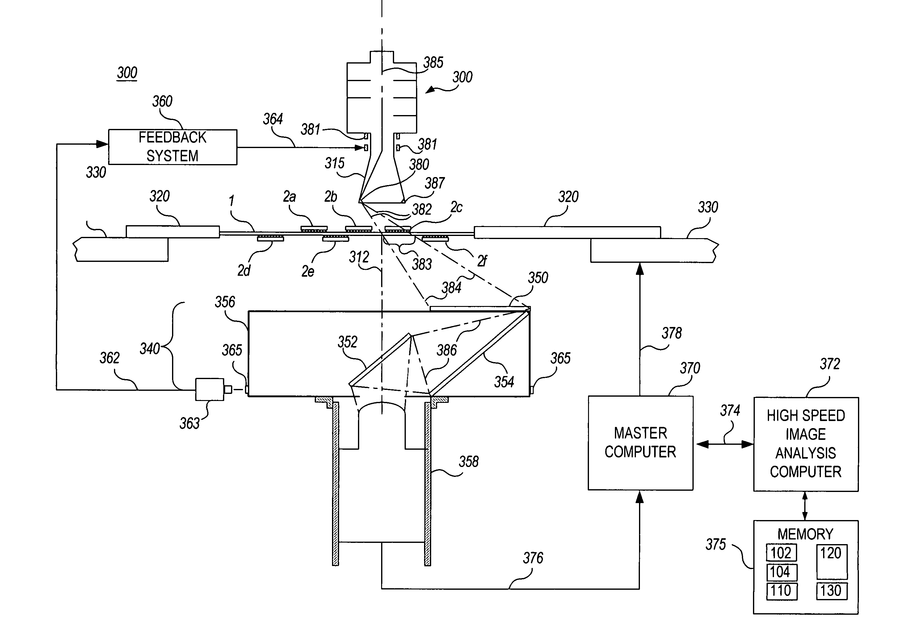
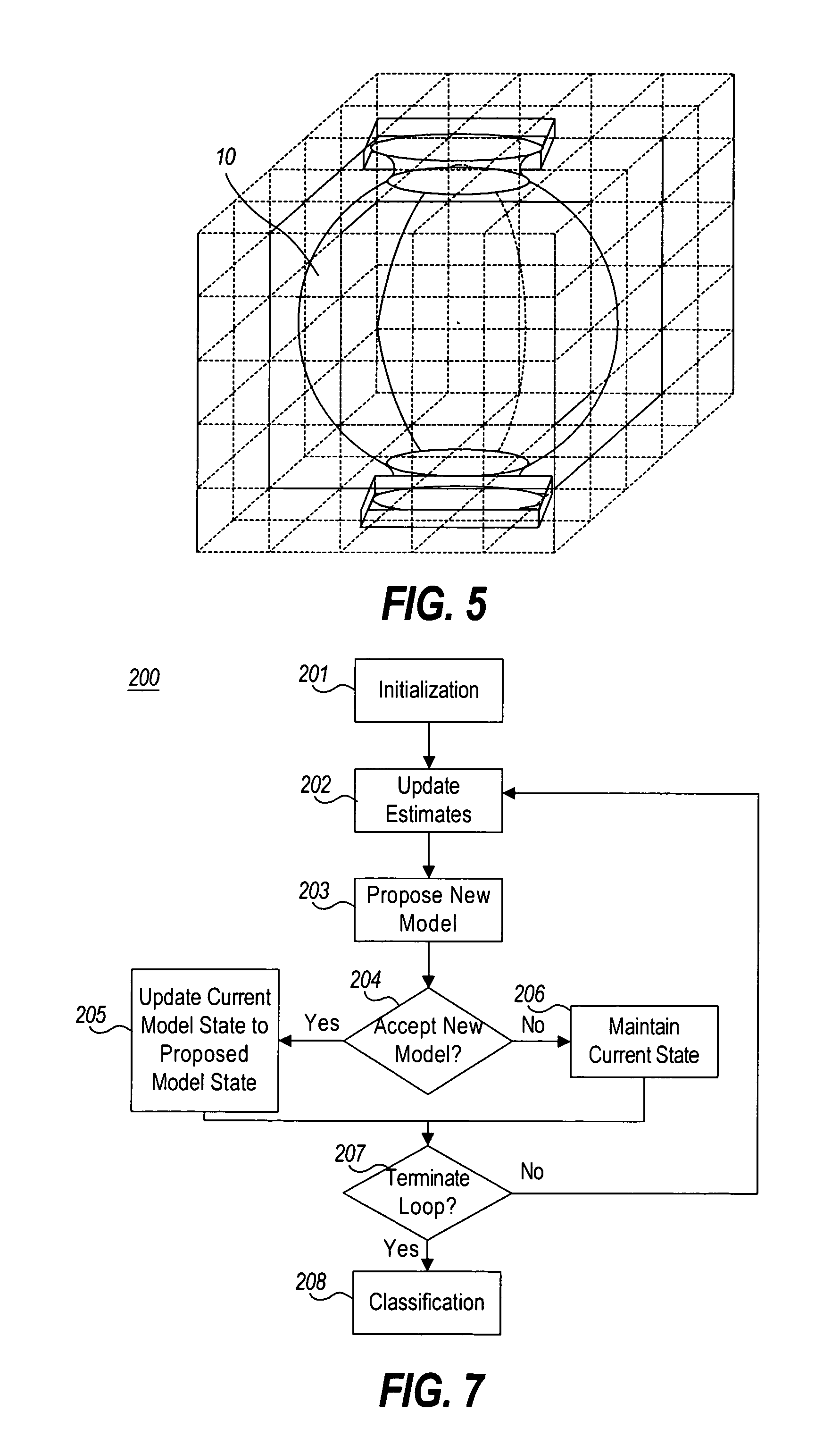
[0042] Turning now to implementation of the present invention, FIG. 6 shows a block diagram of an automated imaging inspection system 100 in accordance with the invention. As shown therein, the automated imaging inspection system 100 includes a reconstruction engine 120 that reconstructs or estimates an object from a set of projections D of an object under inspection on a device under test 106 that are collected by imaging hardware 108 given a highly constrained model M 102 that is constrained by a set of prior information 101, a set of prior probabilities (or “priors”) P(M) 104, and a forward map 110. As used herein, the term “projections” refers to a set of observations of an object of interest in the form of any type of image modality, where each observation is taken from a different viewpoint. In the illustrative embodiment, the projections are in the form of X-ray images of the object of interest.

[0043] The reconstruction engine 12...


PUM


Abstract

A tomographic reconstruction method and system incorporating Bayesian estimation techniques to inspect and classify regions of imaged objects, especially objects of the type typically found in linear, areal, or 3-dimensional arrays. The method and system requires a highly constrained model M that incorporates prior information about the object or objects to be imaged, a set of prior probabilities P(M) of possible instances of the object; a forward map that calculates the probability density P(D|M), and a set of projections D of the object. Using Bayesian estimation, the posterior probability p(M|D) is calculated and an estimated model MEST of the imaged object is generated. Classification of the imaged object into one of a plurality of classifications may be performed based on the estimated model MEST, the posterior probability p(M|D) or MAP function, or calculated expectation values of features of interest of the object.

Description

BACKGROUND OF THE INVENTION [0001] The present invention relates generally to automated imaging inspection techniques, and more particularly to automated inspection of arrays of identical objects using highly constrained tomography and Bayesian estimation. [0002] Tomographic reconstruction from projections provides cross-sectional and 3-dimensional information, and is utilized in many fields including medical imaging, security screening, and automated inspection of manufactured goods. In manufacturing electronic assemblies, for example, solder joints or other interconnects are often not accessible for electrical testing or optical inspection. As a result, imaging using penetrating radiation, e.g. X-rays, is often used for automated inspection of such joints. Tomographic or 3-dimensional methods are required for two reasons. First, modern printed circuit assemblies (PCAs) are typically double-sided, and, in addition, may possess multiple internal layers. As a result, joints or compon...

Claims


Application Information

Patent Timeline
IPC IPC(8): G01N23/04
CPCG01N2223/419G01N23/046
Inventor HEUMANN, JOHN M.FOX, COLINGINES, DAVIDTUFILLARO, NICHOLAS
Owner AGILENT TECH INC
Why Eureka
Try Eureka