Optical body tracker

a body tracker and optical technology, applied in the field of motion tracking, can solve the problems of large errors in the estimation of three-dimensional target location, and achieve the effect of simplifying identification

Inactive Publication Date: 2005-05-19
JOLLY SEVEN SERIES 70 OF ALLIED SECURITY TRUST I
View PDF11 Cites 129 Cited by
  • Summary
  • Abstract
  • Description
  • Claims
  • Application Information

AI Technical Summary

Benefits of technology

[0011] The system tracks active emitting markers through triangulation from data read via multiple linear CCDs through cylindrical lenses. The targets are identified with an improved method that resolves all need for geometrical identification. Each marker is lit in sequence so that it is in sync with a frame capture using the imaging system positioned and oriented so as to provide a basis for computing market three dimensional location.
[0012] The system synchronizes the high-speed imaging of individual markers in the field via three synchronized linear CCD or photodiode arrays to localize position in three dimensions through triangulation techniques. In the preferred embodiment, the imaging system detects an infrared signal which is sent out by the tag controller as part of the tag / marker illumination sequence at the beginning of the first tag position capture time. The controller then traverses through the tags in time sync with each imaging system frame capture cycle. Thus, only one unique tag will be lit during each image capture of the cameras, thereby simplifying identification. Using linear CCD sensors, the frame time (i.e. point acquisition time) is very short, allowing very many markers to be sampled and located sequentially in real time.

Problems solved by technology

This method is important in three dimensional triangulation systems because small errors in spot location estimation on the imaging device translate into larger angular measurement errors and ultimately potentially very large errors in three-dimensional target location estimation.

Method used


Image

  • Optical body tracker
  • Optical body tracker
  • Optical body tracker

Examples


Embodiment Construction

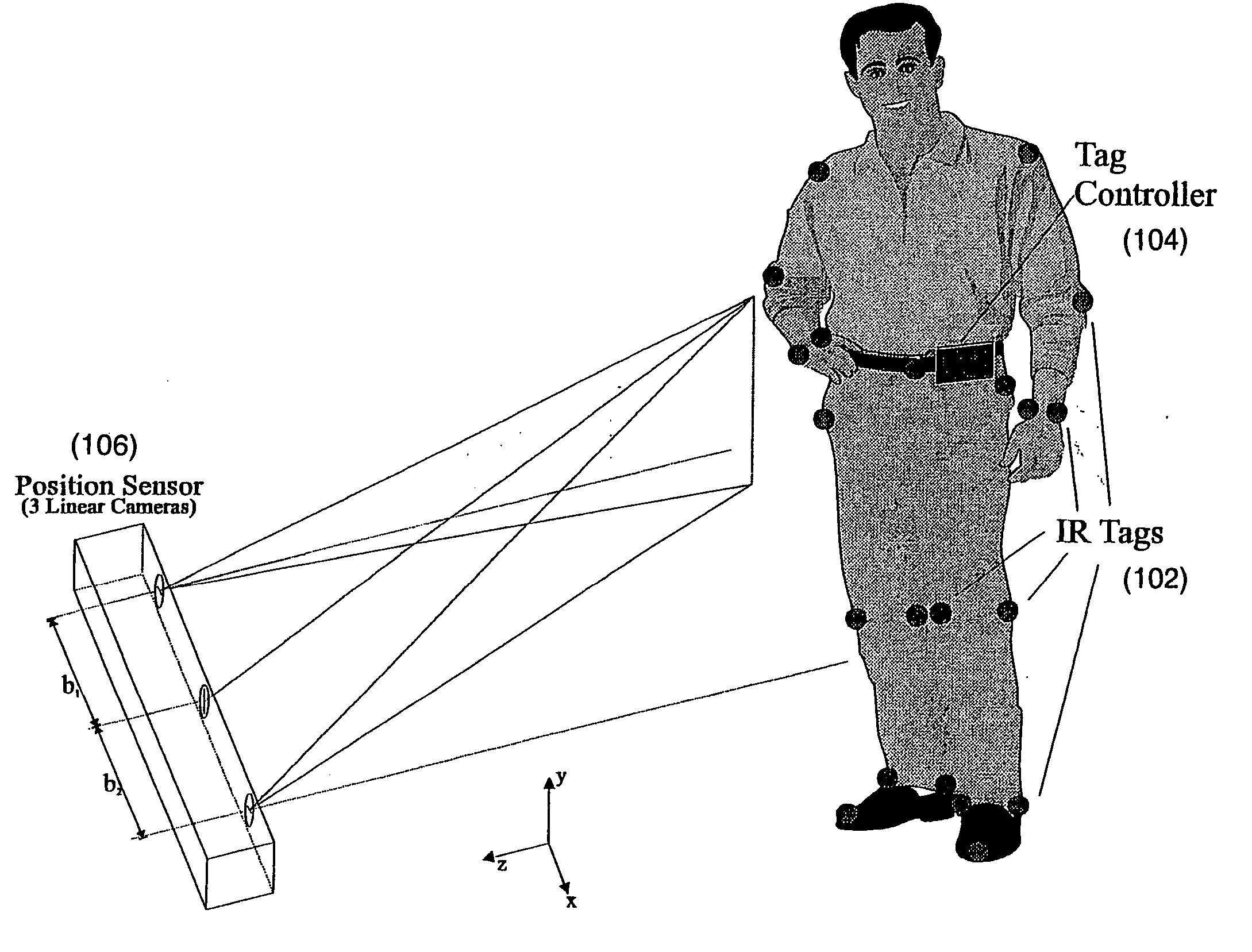
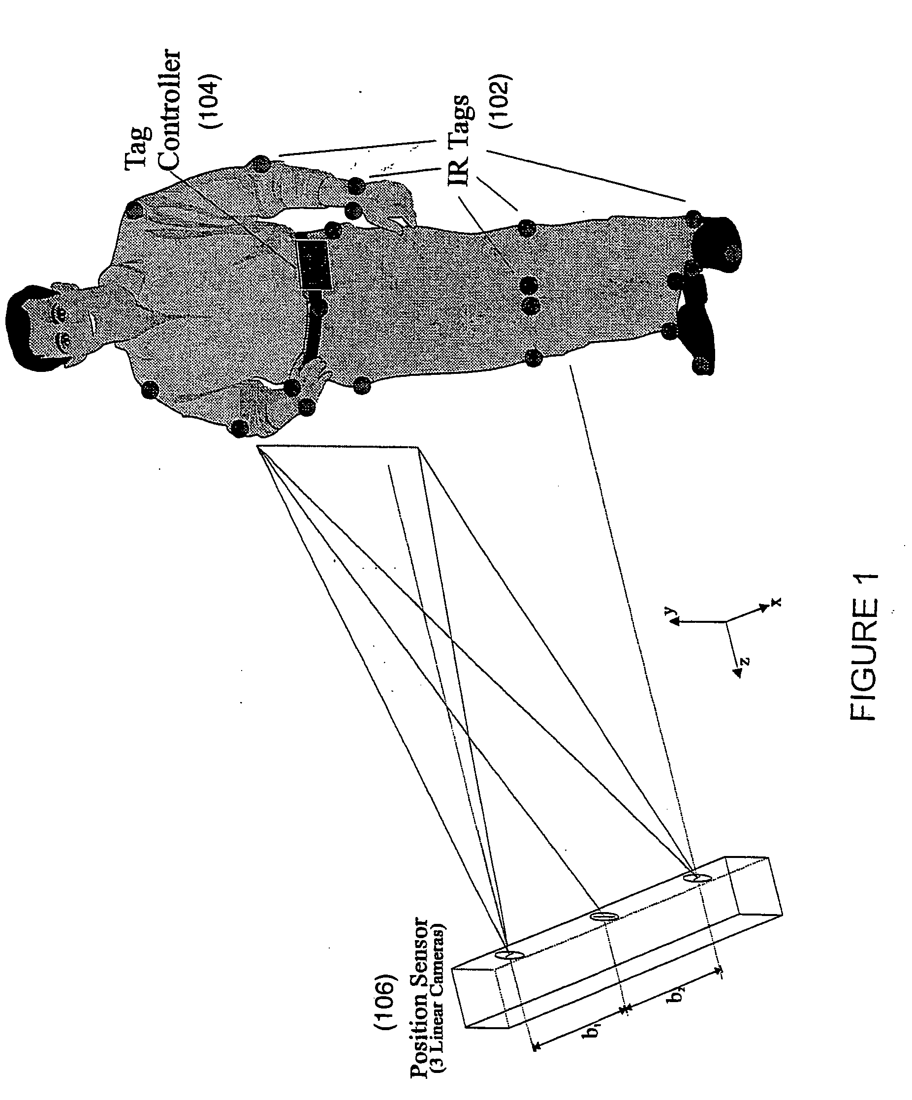
[0020] This invention resides in a real time computer vision system capable of tracking the motion of objects, including the human body or portions thereof. The system is capable of tracking the gestures and behaviors through an unstructured and possibly cluttered environment, then outputs the position of the tracked features in each observed scene.

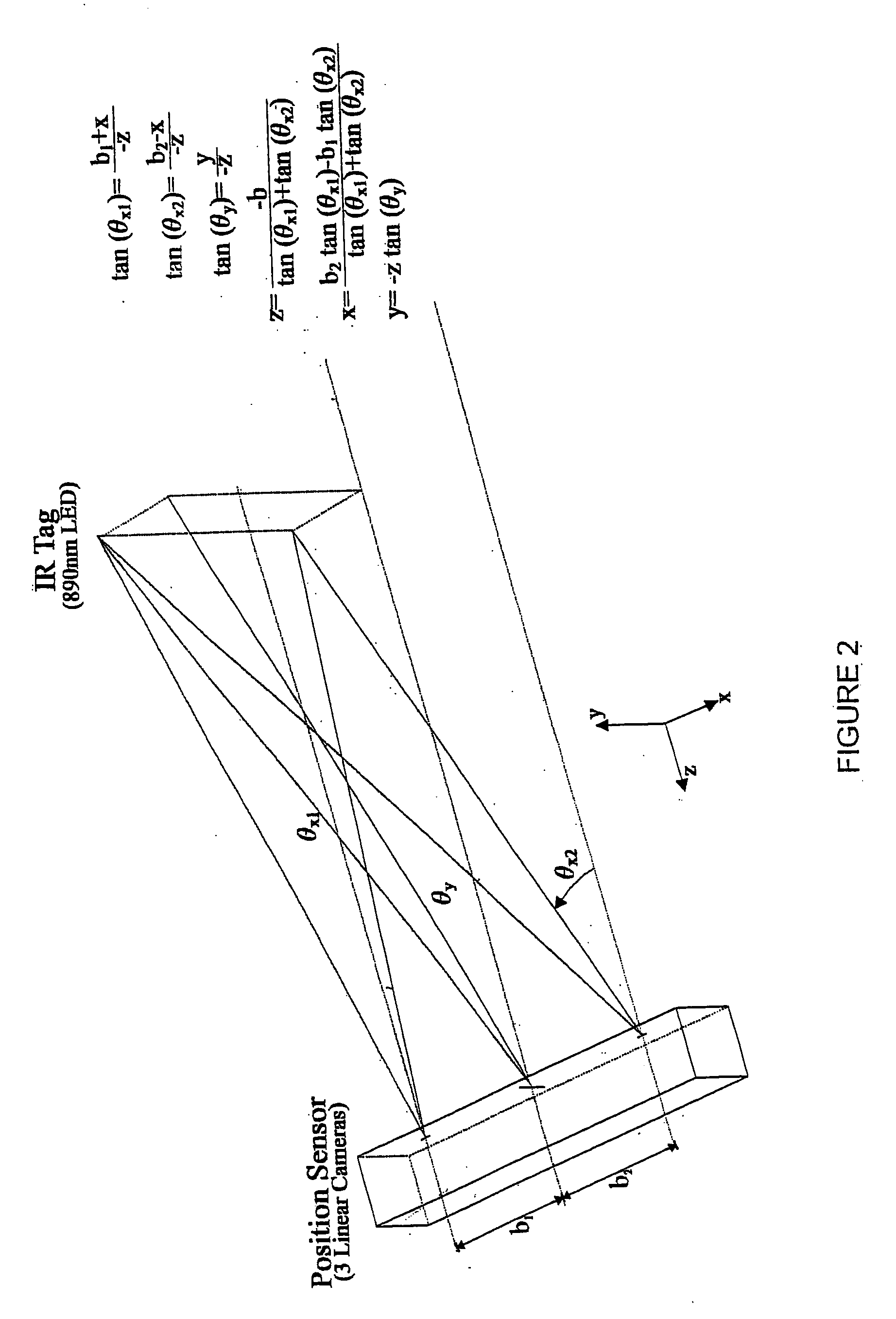
[0021] To determine position in an immersive environment, a user is preferably outfitted with active infrared emitters which are tracked by custom linear cameras. A set of design specifications associated with an implemented system are shown in Table 1:

TABLE 1Design Specification of Existing Body Tracking SystemField of View45 × 45 degreesRange 7 metersAccuracy 2.5 mm @ 5 metersNumbers of sensors1-25530 Sensor scan rate 30 HzCamera frame rate900 HzLatency5 milliseconds maximum

[0022] The implemented system is capable of determining the location of 30 points, 30 times a second with a resolution of 2.5 mm within 5 meters of the tracking s...


PUM


Abstract

An optical system tracks the motion of objects, including the human body or portions thereof using a plurality of three-dimensional active markers based upon triangulation from data read via multiple linear CCDs through cylindrical lenses. Each marker is lit in sequence so that it is in sync with a frame capture using the imaging system positioned and oriented so as to provide a basis for computing three-dimensional location. In the preferred embodiment, the imaging system detects an infrared signal which is sent out by the tag controller as part of the tag/marker illumination sequence at the beginning of the first tag position capture time. The controller then traverses through the tags in time sync with each imaging system frame capture cycle. Thus, only one unique tag will be lit during each image capture of the cameras, thereby simplifying identification. Using linear CCD sensors, the frame time (i.e. point acquisition time) is very short, allowing very many markers to be sampled and located sequentially in real time.

Description

REFERENCE TO PRIOR APPLICATIONS [0001] This application is a continuation-in-part of U.S. patent application Ser. No. 09 / 791,123, filed Feb. 22, 2001, which claims priority of U.S. provisional application Ser. Nos. 60 / 183,995, filed Feb. 22, 2000; 60 / 186,474, filed Mar. 2, 2000; and 60 / 245,034, filed Nov. 1, 2000. U.S. patent application Ser. No. 09 / 791,123 is also a continuation-in-part of U.S. patent application Ser. No. 09 / 371,460, filed Aug. 10, 1999, now U.S. Pat. No. 6,681,031, which claims priority to U.S. Provisional patent application Ser. No. 60 / 096,126, filed Aug. 10, 1998. The entire content of each application and patent is incorporated herein by reference.FIELD OF THE INVENTION [0002] This invention related generally to motion tracking and, in particular, to a system operative to optically monitor and record full-body and partial-body movements. BACKGROUND OF THE INVENTION [0003] Numerous systems exist for measuring object surface or point locations by triangulation ex...

Claims


Application Information

Patent Timeline
Patent Type & Authority Applications(United States)
IPC IPC(8): G06F3/00G06F3/01G06K9/00G06T7/20
CPCA61B5/1127A63F2300/1087G06T7/2033G06K9/00335G06F3/017G06T7/246G06V40/20
Inventor VORONKA, NESTORJACOBUS, CHARLES J.
Owner JOLLY SEVEN SERIES 70 OF ALLIED SECURITY TRUST I
Why Eureka
Try Eureka